Force notes
Force notes
The following text is used only for teaching, research, scholarship, educational use and informative purpose following the fair use principles.
We thank the authors of the texts and the source web site that give us the opportunity to share their knowledge
Physics
Force notes
Force:
In Physics, Force is defined to be the agent that causes a body to change its state of motion.
A body changes its state of motion if it is:
- at rest and begins to move.
- moving and changes its speed.
- moving and changes its direction of movement.
Force is the source of all motion, or more precisely, the source of any change in an object's motion.
We say that a force has acted on a body if the body changes its state of motion in any way. This statement is the inverse of Newton's First Law.
Force is a man-made concept created by Newton to explain the source of a body's motion. Newton's Second Law is better viewed as the definition of Force, rather than a true law of Nature. The utility of such a concept is that it produces a model which can be used to explain and predict the motion of objects.
Do forces exist ? I do not know, but I do know that it is a useful concept that brings meaning and order to the motion and interaction of bodies.
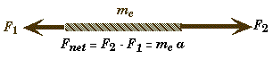
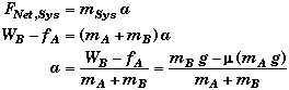
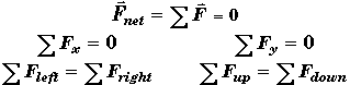
The Net Force
- The net force is the vector sum of all the individual forces acting on a system.
![]()
- The net force is not a "real force", having an existence independent of the other forces acting on a body. It is symbol representing their mathematical sum.
- For any one of the forces (say the ith force) acting on an object,
![]()
- When there is only one force acting on an object, which is symbolized by F , then the net force is equal to that one force, and the second law can be expressed (as it often is):
![]()
Physical Meaning of the Superposition of Forces:
The action of all the forces acting on a system can be replaced with a single force that produces the same results, provided that this single force's magnitude and direction are identical with the magnitude and direction of the net force -- the vector sum of all the forces acting on the system.
Useful Corollary:
Any force can be replaced by the action of two forces at right angles to each other provided their vector sum is equal to the original force. Often this can make a problem simpler to solve. The magnitude of these two forces are equal to the components of the original force along the axes chosen.
External and Internal Forces:
Any given force can be either an external force or an internal force depending upon how the system is defined.
A system can be either a single object, or a group of objects. The objects do not even have to be bound or interacting with each other to form a system. However, it usually makes things a lot simpler if they are connected in some way.
Many times the constraints between the sub-bodies that comprise the system can be expressed as a mathematical relationship which will be useful when solving the problem.
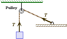
Example: Simple Pendulum
A bob is connected to the end of a massless cord that is connected to the ceiling.
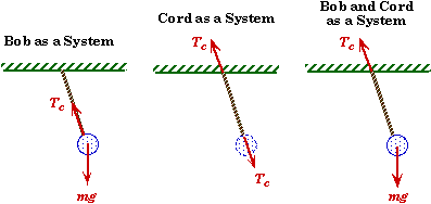
If one chooses the bob to be the system, then both the weight of the bob, mg, and the tension in the cord, Tc , are external forces.
If one chooses the cord to be the system, then there are two external forces acting on the cord: the force that the ceiling exerts on the cord and the force that the bob exerts on the cord. Both of these forces are equal in magnitude and equal to the tension in the cord by Newton's Third Law. If the cord were not massless, then there would be a third external force acting on this system, the weight of the cord. It would also mean that the two forces acting at its end would no longer be equal.
If one chooses both the bob and the cord to be a system, then there are two external forces acting on this system, the force of gravity on the bob and the force that the ceiling exerts on the cord. The forces that the cord exerts on the bob and the force that the bob exerts on the cord become internal force in this system. Moreover, by Newton's Third Law they are equal in magnitude and opposite in direction so that even if you considered them to be external forces, they would cancel each other out.
If you considered the bob, the cord, the ceiling, and the Earth to the system, then the only external forces acting on the system would be the gravitational force of the Moon and the Sun on this system. The weight of the bob would become an internal force balancing the force (also internal) that the bob exerts on the Earth. By Newton's Third Law the bob pulls on the Earth with a force equal to that which the Earth pulls on the bob, but in the opposite direction. It may be hard to believe, but it's true. You never notice it because the Earth's mass is so much bigger than the mass of ordinary objects.
Newton's First Law: The Law of Inertia
* The natural state of motion of a force-free system is a state of uniform motion in a straight line.
* An object moving at a constant speed needs no net external force to keep it moving; its inertia keeps it moving at a constant speed in a straight line.
* If the sum of all the forces acting on a system is zero, meaning that the magnitudes of the forces cancel each other out, then the net force on the system is zero. The system will then move at a constant velocity in a straight line if it is moving, or remain at rest if it is at rest.
* If either the magnitude or direction of an object's velocity changes, then there must be some force impressed upon the object. This is actually the definition of when there is a non-zero force acting on an object.
* For a system to be in a state of mechanical equilibrium, the vector sum of all the forces acting upon the system must add up to zero.
![]()
Newton's Second Law:
![]()
- The change in an object's state of motion - its acceleration - is proportional to the magnitude of the net force acting on the object along the direction of the net force.
- When ever the net force acting on a body is not zero, the body will accelerate in the direction of the net force. The magnitude of the body's acceleration is equal to the value of the net force divided by the body's mass.
- This is a vector equation so you will normally need to resolve the forces in to vector components before you can apply Newton Second Law to solve a problem.
UNITS of FORCE: SI: (Newtons) N = kg.m/s2
Free-Body Force Diagrams
* The purpose of a free-body force diagram is to assist you in trying to determine the net force acting on a body. It is only the net force to which Newton's Second Law can be applied and not each individual force separately.
Useful mental overseer questions to reflect on are:
- How shall I define the system?
- What are the forces acting on the system?
- In which directions are they pushing or pulling on the system?
- Do I have them all? Do I have too many?
- Are any of the forces I have sketched non-existent? What is the source of the force?
Constructing a free-body force diagram:
* Select an object or group of objects to focus on as the "body", i.e. the system.
* Sketch the body by itself, "free" of its surroundings. The body could be represented by a single point located at the body's center of mass.
* Draw only those forces that are acting directly on the body. Include both the magnitude and the direction of these forces.
* Except for rotational problems, you can normally sketch the forces as though they were acting through a single point at the center of mass of the body. It is useful to draw the force-vectors with their tails at the center of mass.
* Do not include any forces that the body exerts on it surroundings, they do not act on the body. However, there is always an equal reaction force acting on the body.
*For a compound body you do not need to include any internal forces acting between the body's subparts, since these internal forces come in action-reaction pairs which cancel each other out because of Newton's Third Law.
*Choose a coordinate system and sketch it on the free-body diagram. If you choose one of the axes to be parallel to the object's acceleration, it can sometimes simplify the equations you have to solve.
Example 1:
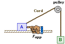 Suppose that a block is pushed to the left on a surface with friction by a horizontally applied force, and that the block is connected by a cord passing through a frictionless pulley to a hanging weight.
Let T represent the tension in the cord and f the force of friction acting on the block.
Free-Body Diagram for Block A |
Free-Body Diagram |
|
|

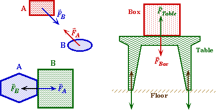
Example 2.
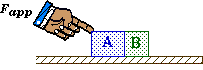
Suppose two blocks of different masses are pushed along a frictionless surface by a force applied at an angle.
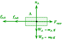
Let FBA be the force that block B exerts on block A, and FAB be the force that block A exerts on block B.
Free-Body Diagram for Block A |
Free-Body Diagram for Block B |
|
|
Free-Body Diagram for the System of Both Blocks |
|
|
|
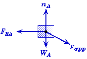
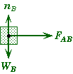
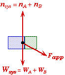
Observe that the applied force Fapp only acts on block A and not block B. It does affect block B but it does not act directly upon B. Changing Fapp would change the magnitude of FAB, the force that block A exerts on B.
Also observe that when both blocks together are considered to be a single system, then the FAB and FBA become internal forces and cancel each other out.
Types of Forces
CATEGORY |
SYMBOL or TAG |
General Force |
F |
Weight/Gravity |
W = mg |
Tension in Cord/Rope |
Fc = T |
Human Push or Pull |
Fapp |
Surface Friction |
Ff = f = m n |
Normal Contact Force |
n |
Spring |
Fs = -k s |
Air Drag |
FDrag = Fair =1/2 C A v2 |
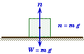
Weight of a Body
- In physics the weight of an object is equal to the force that the Earth exerts on the object.
- Since all objects have the same downward acceleration (in the absence of air resistance) of g = 9.80 m/s2, the force of gravity on a falling object is equal to Fgrav = m g. Normally, we symbolize an object's weight with the symbol W . Gravity exerts this force on an object regardless of the object's motion or lack of motion.
W = m g
- In everyday usage we normally associate the weight of an object with the net downward force on an object and not just the force of gravity. In a swimming pool we would say we weigh less because of the buoyant force of the water, but we really don't weigh less. We also say an astronaut circling the Earth is weightless even though the Earth still exerts a force on the astronaut to keep him in orbit.
- The mass of an object and the weight of an object are not the same quantities . Near the surface of the Earth they only differ by a fixed amount, namely g = 9.80 m/s2. It is common to not distinguish between the these two different quantities in everyday conservation.
- Technically, the English system's unit for mass is not pounds (that is force) but slugs (which nobody ever uses except in a physics course).
Tension in a Cord
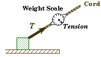 The force exerted by the end of a taut cord, string, or wire connected to a body is called the Tension. The direction of the tension-force is exerted along the direction of the cord. The magnitude of the tension is equal to the force that one would measure if the cord were cut and a force spring-scale were inserted.
- It is normally assumed that the cord is both massless and stretchless. Under these conditions the tension is transmitted through the cord unabated. This means that the forces at both ends of a cord have the same in magnitude even if the cord changes direction through a pulley.
- At any moment the velocity and acceleration of two moving objects will be the same provided they are connected by a massless, stretchless, taut-cord.
- If the cord was not light, then the forces at both ends would have to be different. If the system is at rest (or moving at a constant speed) then the difference between the two end forces would have to be equal to the force needed to suspend the cord weight of the coard. If the system was accelerating, then the two end force would have to be different to produce a non-zero net force on the cord.
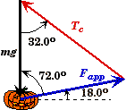
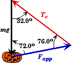
Hanging Pushed Pumpkin Problem
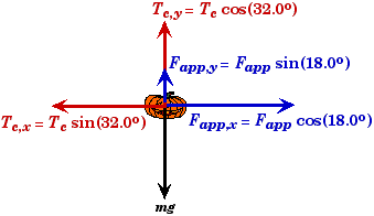
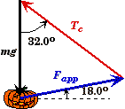
A pumpkin of unknown mass is suspended by a cord attached to the celing and pushed away from vertical. When a 24.0 N force is applied to the pumpkin at an angle of 18.00 to horizontal, the pumpkin will remain in equilibrium when the cord makes an angle of 32.00 with the vertical |
|
What is the tension in the cord when the pumpkin is in equilibrium ? |
|
What is the mass of the pumpkin ? |
|
Sketch and Process:
A pumpkin hangs stationary at an angle when a force is used to push the pumpkin to one side.
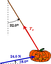
Givens and Labels:
Fapp |
= 24.0 N |
(Magnitude of the Force applied) |
qF |
= 18.00 |
(Applied force's angle relative to horizontal) |
Tc |
= ? |
(Tension in the cord) |
qc |
= 32.00 |
(Angle cord makes with the vertical) |
mp |
= ? |
(Mass of the pumpkin) |
Fnet |
= 0 |
(Net force on the pumpkin in equilibrium) |
Frame of Reference:
The system on which the forces act is the pumpkin.
Relevant Physics:
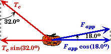
There are three forces acting on the pumpkin, the tension in the cord Tc, the applied force Fapp, and the force of gravity mg. In order for the pumpkin to not move, the vector sum of these three forces must add to zero so that there is no net force on the pumpkin.
We assume that these forces act through the center of mass of the pumpkin. The free-body force diagram:
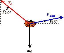 Free-body Forces acting on the Pumpkin. |
= |
|
Since the pumpkin is in static equilibrium:
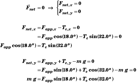
Alternately, we know that the sum of the three force vectors must add to zero.
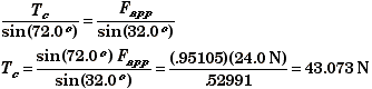
(A) Find Tc.
First resolve the forces acting on the pumpkin into horizontal and vertical components.

The horizontal component of the tension in the cord Tc,x must be equal to the horizontal component of the applied force Fapp,x for the pumpkin to be in static equilibrium.
![]()
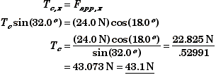
- Since gravity only acts in the downward direction, it can have no effect on the horizontal equilibrium. This means that the magnitude of the tension in the cord depends solely on the applied force - both its magnitude and direction. Gravity, will determine the angle were equilibrium will occur.
We could check our results by applying the Law of Sines to the vector sum of the forces. Since the forces add up to zero, the vectors forms triangle. The angle opposite the tension is 90.0o - 18.0o = 72.0o.
(B) Find mp.
First we resolve the forces acting on the pumpkin into vertical and horizontal components. The sum of both the vertical components and the applied force Fapp,y and the tension in the cord Tc,y must equal to the weight of the pumpkin mg for the net force in the vertical direction to be equal to zero.

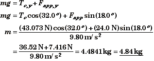
If we were given the mass of the pumpkin, then this equation would determine the angle at which the pumpkin would be in equilibrium.
To check our results we could also use either the Law of Sines or the Law of Cosines. Using the Law of Cosines, we see that the angle opposite the gravity is 180o - 32.0o - 72.0o = 76.0o.
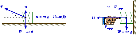
The Applied Force: Fapp
- Any force could be considered to be an applied force, but we usally let Fapp stand for a force applied by a person or an action which directly pushs or pulls on a system.
- When we humans push or pull on an object we exert a force whose magnitude and direction are determined by us. This means that the magnitude and direction of such forces can never be calculated independently, like the weight of an object can be found from W = mg. Applied forces either have to be given or found using Newton's Laws. For example, if you pull down on a spring-scale and it reads 7.80 N, then you know by Newton's Third Law that the force you applied must be equal to that of the stretched spring.
- The applied force is just one of the many forces that could be acting on an object. It is not the big cheese, meaning Fapp is not equal to Fnet. If it is the only force acting on an object, then the applied force will be equal to the net force by default. It is extremely tempting to want to set Fapp equal to ma, but here again Fapp is not equal to ma unless it is the only force. This tendency may arise from the observation that when you personally change the magnitude of the force you are applying, the system's behavior will change. However, this is also true for any other force acting on the system--change it and the subsequent motion will change. An object's acceleration is a consequence of ALL the forces acting on a system, not just the applied force.
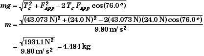
Contact Forces: Force of Friction and Normal Force
|
|
Fc |
= Contact Force between two surfaces. |
|
= Force that the surface of one object exerts on the surface of another object. |
n |
= Normal Force. |
|
= Perpendicular component of the contact force which is always at 90oto the contact surface. |
|
= "Force pressing the surfaces together." |
f |
= Force of friction. |
|
= Parallel component of the contact force. |
|
= "Force of sliding or static friction" |
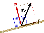
For Objects at Rest:
f £ µs n |
|
µs= Coefficient of static friction |
fmax = µs n
For Objects in Motion:
f = µk n |
|
µk= Coefficient of kinetic friction |

Force of Friction
* When the surface of one object slides across the surface of another object and some other force is pressing the surfaces together, a drag force is created between the two surfaces that is parallel to the surfaces.
For Objects at Rest: Static Friction
f £ ms n |
fmax = ms n |
f |
= Force of Friction. SI: N |
ms |
|
n |
= The normal force pressing the surfaces together. SI: N |
- The coefficient of static friction depends upon the roughness of the surfaces.
- The coefficient of static friction does not depend upon contact surface area, provided the two surfaces are made of dissimilar enough material so that any cohesive force between the two surfaces is small.
- The force of static friction (like the normal force) is a reaction force in that its value depends upon the magnitude of some external force trying to push the object along the surface.
- The force of friction is always oppsite to direction of the other forces imposed.
- The force of static friction increases up to a maximum value, after which the object "breaks loose" and begins to start moving.
For Objects in Motion: Kinetic Friction
f = mkn
f |
= Force of Friction. SI: N |
mk |
= Coefficient of kinetic friction. SI: Dimensionless |
n |
= The normal force pressing the surfaces together. SI: N |
- The coefficient of kinetic friction (like the static coefficient) depends upon the roughness of the surfaces. However it is generally smaller in value than the static coefficient.
mk< ms
- For relative velocities in the range of cm/s to m/s (typical ranges we will encounter) the coefficient of kinetic friction is approximately constant.
Direction of the Force of Friction
* The direction of the force of friction is such that it opposes the direction of motion that an object would move if there were no frictional force acting on the object.
Kinetic Friction:
* The force of friction f is always opposite the direction the object is moving in the problem.
![]()
Static Friction:
* It is not always clear in which direction the force of friction is acting, since the object is at rest.
* The best way to decide the direction is to consider what the object would do if there were no friction acting on the object. If the object would move, then the direction of the force of friction f will be opposite the movement. If the object would not move when there is no friction, then the force of friction is zero.
* The magnitude and direction of the static force of friction can be anywhere from -msn to +msn. In general, one cannot determine the magnitude of the static force of friction by some simple equation without looking at the dynamics of the problem using a free-body force diagram.
For static equilibrium, Fnet = 0. If F'net is the net force on the object when there is no friction, then
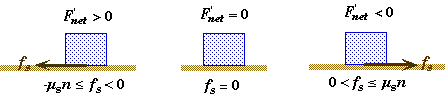
Normal Force
* The normal force on a body is generally associated with the force that the surface of one body exerts on the surface of another body in the absence of any frictional forces between the two surfaces.
* The normal force is always perpendicular to the surfaces in contact. This is the origin of its name - normal to the surface.
* The normal force is an action-reaction force. A surface will not exert a normal force on an object in contact with it unless some other external force pushes the object into the surface.
* The atoms in the surface are compressed microscopically to create the normal force. The surface deforms imperceptibly and produces a reaction force equal to the force pressing the object into the surface.
* For an object sitting on a horizontal surface, the normal force will be equal to the weight of the object.
* The normal force is not always equal to the weight of an object; it is the force pressing the surfaces together.
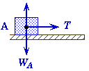
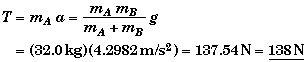
Sliding Block and Hanging Block
A 32.0 kg block rests on a horizontal frictionless table top. This block is connected to a 25.0 kg block hanging off the edge of the table by a rope that passes over a light frictionless pulley. Initially a peg holds the first block in place. |
|
(A) |
What is the tension in the rope before the peg is removed ? |
(B) |
What is the acceleration of either block after the peg is removed ? (But before the hanging block hits the floor.) |
What is the tension in the rope after the peg is removed and the blocks are accelerating ? |
|
What is the magnitude and direction of the force that the pulley exerts on the rope after the peg is removed and the blocks are accelerating ? |
|
Sketch and Process:
Block A is pulled across a horizontal frictionless surface by the tension in a rope that is connected to block B. Block B falls downwards under the influence of gravity but is retarded from falling freely by the tension in the rope due to its connection to block A. |
|
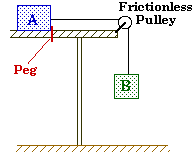
Givens and Labels:
Approximate Values of the Coefficient of Friction
Surfaces in Contact |
Static µs |
Kinetic µk |
Teflon on Teflon |
= .04 |
= .04 |
Rubber on Concrete (wet) |
@ .30 |
@ .25 |
Rubber on Concrete (dry) |
@ 1 |
@ .8 |
Steal on Steal |
= .74 |
= .57 |
Metal on Metal (lubricated) |
@ .15 |
@ .06 |
Human Joints (Synovial lubricant) |
@ .01 |
@ .003 |
Ski Board (waxed on wet snow) |
@ .14 |
@ .1 |
Ski Board (waxed on dry/power snow) |
@ .14 |
@ .04 |
Ice on Ice |
=.1 |
= .03 |
Wood on Wood (Rough) |
@ .5 |
@ .4 |
mA |
= 32.0 kg |
(Mass of block resting on table, block A) |
mB |
= 25.0 kg |
(Mass of block hanging from table, block B) |
T |
= ? |
(Tension in the cord) |
a |
= ? |
(Acceleration of either body) |
WB |
= mBg |
(Weight of block B) |
Reference Frame:
Any rest frame such as the table top will do.
We choose the direction of motion of block A on the table top to be the positive horizontal direction. Because we usually take directions to the right to be positive we will arrange our sketch of the process so that the motion of this block is to the right.
Since the magnitude of the acceleration of the two blocks is the same, we choose down - the direction of the motion of hanging block B - as the positive direction. If you were to choose up as the positive direction, then the acceleration of the hanging block would be negative while the acceleration of the block on the table would be positive.
Relevant Physics:
* The length of the rope is assumed to remain constant - it does not stretch. This means that the magnitude of the acceleration (or speed) of one block will be the same as that of the other block even though they are moving in different directions. Thus aA = aB = aSysten, and we can use one symbol "a" to denote the acceleration of either block.
*The rope is assumed to be massless, so that it has no effect on the inertia of the system.
*The massless, frictionless pulley also has no effect on the system. Its only influence is to redirect the tension in the rope by 90o.
*The trick to solving this type of problem is to figure out what forces are acting on the blocks, so that one can generate an expression for the net force to use in Newton's Second Law. To this end, a free-body force diagram is very useful.
*It is also useful (and necessary) to consider each block as a sperate system. Newton's Second Law of motion can be applied to block A alone, block B alone, the pulley alone, or some combination, such as blocks A and B together as a system.
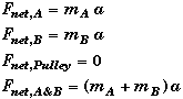
System: Block A Block B Pulley Both Blocks |
Newtons Second Law: |
Free-body diagrams:
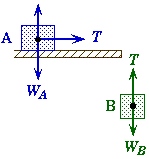 |
|
Free-Body Force Diagrams for the two blocks and the pulley considered as independent systems. |
|

Once we know the forces we can write down Newton Second Law for each system. Since Newton's Second Law is a vector equation we will also need express in component form in both the x and y direction. Newton's Second Law equation for each system (after the peg is removed) becomes,
These are basic equations that you can apply to solve this problem.
- Note that the system of both blocks is the easiest to use if you are only interested in finding the acceleration alone. You cannot use this combined system by itself to find the tension in the rope, since the tension is an internal force in this system.
- Also note these equations are not all independent of each other. For example, if you add the x-component equation for block A and the y-component equation for block B you will get the same expression as the combined system for both blocks A&B.
(A) Find the tension T when the system is at rest.
Focus on block B as a system by itself to apply Newton Second Law. Before the peg is removed a = 0, and the net force on block B is zero. There are only two forces acting on block B, gravity and the tension. The net force is their difference.
Appling this to block B's Second Law equation and solving for T, |
|
|
|
Free Body diagram |
|
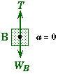
Since the tension in the rope is the same everywhere along its length, the horizontal force that the peg exerts on block A must also be equal to the tension in the rope by Newton's Third Law.
- Do no be fooled into believing that this is a general result, i.e. that the tension always equals weight. This is only true because the system is at rest. If block B is accelerating downward then the Tension in the cord has to be less than 245 N or else the net force on block B would not be greater than zero.
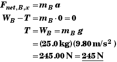
(B&C) Find the acceleration a and the tension T when the blocks are moving.
After the peg is removed a > 0.
Focusing on block B as a system Newton Second Law in component form becomes: |
|
|
|
Free Body diagram |
|
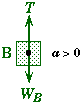
This implies that the tension in the rope will not be equal to the weight of block B after the blocks start moving. The tension will be less. In fact the only way that block B could accelerate downwards is if the weight of B is greater than the force up, the tension.
Although this equation is interesting, we cannot use it by itself to find T since this equation contains another unknown, the acceleration a. We need another equation relating a and T together.
Focusing on block A as a system, the block's motion is horizontal and the only force acting on it horizontally is the tension in rope.
Newton's Second Law for block A |
|
|
|
Free Body diagram |
|
This gives another equation relating a and T. Combining these two equations we can find either a or T.
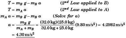
Knowing a we can now find the tension,
You could use the equation for block B to also find the tension as a self consistency check.
Alternate Method:
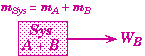 Choose both blocks together as a single system.
* Since the tension becomes an internal force in this system, the tension has no effect on the combined system. The tension on A is equal and opposite to the tension on B.
* The only external force on the combined system is the weight of block B alone. (The weight of A is canceled by the normal force of the table on A.)
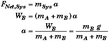
It is simpler to find a by this method since the unknown T is eliminated because it is an internal force.
Note that since we found the same answer using two different approaches its likely that our solution is correct.
Had there been friction between block A and the table top, the resulting acceleration would be even less. The frictional force on A would act as another external force.
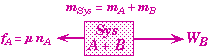
Free Body diagram of both blocks as a system with friction
(D) Find the force that the pulley exerts on the rope Fp and the 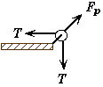 direction of the force qp.
The net force on the pulley is zero since it is not accelerating. The external forces on the pulley are the rope tension T (which pulls in two directions) and force that the table exerts on the pulley Fp.
Had the pulley not been frictionless, then the tension in the cords would not be the same on both sides of the pulley.
Spring Force - Hooke's Law
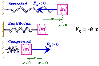
Fs |
= Force exerted by the spring. SI: N |
k |
= Spring Constant. SI: N/m |
|
|
x |
= Displacement from equilibrium position. SI: m |
* The negative sign indicates that the spring force is a restoring force, i.e. the force Fs always acts in the opposite direction from the direction in which the system is displaced.
* The origin has to be placed at the position where the spring system would be in equilibrium for the equation Fs= -k x to be valid. This is the location where the net force on the object to which the spring is attached is equal to zero. If not, then Fs= -k (x - xo) where xo is equilibrium position relative to the origin.
*Springs are normally assumed to be massless so that their inertia can be neglected. This also means that the forces exerted by both ends of the spring are the same but in opposite directions.
*Had the direction for the positive values of x been taken to the left rather than the right then Fs= k x. To avoid confusion we will always take the direction for positive values of x in such a way that Fs= -k x.
Drag Force in a Medium
- The force exerted on a body moving in a medium like air or water depends in a complex way upon the velocity of the body relative to the medium, the viscosity and density of the medium, the shape of the body, and the roughness of its surface.
- The most common method of mathematically modeling the drag force is the equation,
![]()
FD |
= Drag Force. SI: N |
CD |
|
A |
= Coss-sectional Area perpendicular to the flow. SI: m2 |
r |
= Density of the medium. SI: kg/m3 |
v |
= Velocity of the body relative to the medium. SI: m/s |
- The direction of the drag force is always opposite the direction of the body's velocity.
- The drag coefficient CD is not constant. CD depends upon the velocity of the body, viscosity of the medium, the shape of the body, and the roughness of the body's surface.
- The Reynolds number has been found to be a useful dimensionless number that can characterize the drag coefficient's dependence upon the velocity. The Reynolds number is basically the ratio of the inertial force of the medium over its viscous force.
![]()
Re |
= Reynolds number. SI: Dimensionless |
L |
= Characteristic length of the body along the direction of flow. SI: m |
h |
= Dynamic Viscosity of the medium. SI: N s/m2 |
r |
= Density of the medium. SI: kg/m3 |
v |
= Velocity of the body relative to the medium. SI: m/s |
- For small values of the Reynolds number - called laminar flow since the flow is nonturbulant - the drag coefficient is inversely proportional to the velocity. This means that the drag force is only proportional to the body's velocity.
![]()
- When the flow is turbulent the Reynolds number is large, and the drag coefficient CD is approximately constant. This is the quadratic model of fluid resistance, in that the drag force is dependent on the square of the velocity.
![]()
- Note that the frictional force between two surfaces is an example of a situation in which the drag force is constant and does not depend upon the body's velocity or contact surface area.
Newton's Third Law:![]()
* For every action there is an equal and opposite reaction.
* When one body exerts a force on a second body, then the second body will exert a force on the first body equal in magnitude but opposite in direction.
* If object A exerts a force equal to ![]() on an object B, then the object B will always exert an equal but oppositely directed force
on an object B, then the object B will always exert an equal but oppositely directed force ![]() on A,
on A,
![]()
* The action-reaction forces do not act on the same body.
Pushing Stacked Blocks
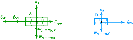
A 650 g styrofoam block is stacked on top of another 850 g styrofoam block. Both blocks rest on a horizontal surface made of styrofoam that is locked in place. An applied force Fapp pushes horizontally on the bottom block. To simplify the problem we will assume that the coefficient of friction is the same between all the surfaces, with a coefficient of static friction of .490 and a coefficient of kinetic friction of .330. |
|
(A) |
What is the minimum force needed to set the blocks into motion ? What is the initial acceleration of the blocks when they begin to move ? |
(B) |
What is the maximum acceleration that the bottom block can have without the top block beginning to slip ? What applied force will produce this acceleration ? |
(C) |
If the applied force is equal to 15.0 N what is the acceleration of each block ? |
(D) |
If the bottom block has a width of 3.00 m, the top block a width of 1.50 m, and the blocks are centered over each other initially, and if the force applied to the bottom block is 15.0 N, how long will it take for the top block to slide to the point where the back ends of the two blocks are lined up with each other ? |
Sketch and Process:
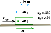
The bottom block of two stacked blocks is pushed by a horizontally applied force.
Frame of Reference:
A stationary observer whose x-origin is located along the vertical line through the centers of the two blocks.
We start the clock when the force is first applied and the blocks begin to accelerate (even if a = 0).
Givens and Labels
To codify the blocks, we will call the block on the bottom Block A and the block on the top Block B.
mA |
=.850 kg |
(Mass of bottom block A.) |
mB |
=.650 kg |
(Mass of top block B.) |
Fapp |
= ? |
(The magnitude of the applied force.) |
|
= 15 N |
(The magnitude of the applied force for parts C and D.) |
ms |
= .490 |
(Coefficient of static friction between all surfaces.) |
mk |
= .330 |
(Coefficient of kinetic friction between all surfaces.) |
fA/S |
= ? |
(Magnitude of the frictional force that the surface exerts on A.) |
fA/B |
= ? |
(Magnitude of the frictional force that B exerts on A.) |
fB/A |
= fA/B= ? |
(Magnitude of the frictional force that A exerts on B.) |
amax |
= ? |
(Maximum acceleration of bottom block without top block slipping.) |
wA |
= 3.00 m |
(Width of the bottom block A.) |
wB |
= 1.50 m |
(Width of the top block B.) |
t |
= ? |
(Time for the top block to slide to the end of the bottom block.) |
Relevant Physics
The equations that describe the behavior of this system are not simple. They are generated from a few equation but you must first understand the behavior of this system before you can generate the equation needed. It would be a good idea for you to experiment with a real system of two stacked blocks. This will give you a feel for what to expect if you push on the bottom block with different amounts of force.
The key to solving this problem is in having some understanding of what is happening so that you can know how to identify the forces acting on each block so that Newton 2nd Law can be applied. If the blocks are moving together without any slipping between the blocks, then the natural system is that of both blocks acting together as a unit. If the two blocks have different motions, then you could focus on each block separately and apply Newton's 2nd Law to each block to determine its individual acceleration. For any system you choose, it is important to sketch the free-body force diagram for system chosen.
You should be aware that the presentation which follows has been organized into logical parts. This was not the way I originally solved the problem. I examined one aspect for a while, and then another aspect, until I was able to arrive at a solution. Only after I had already solved the problem was I able to organize my answers into neatly packaged sections. Moreover, I was not able to clearly identify all the unknowns needed to solve the problem before I began. I added these to the "Given and Labels" list as I went along.
Normal Forces:
Since there is no vertical movement, the net force on each block in the vertical direction will be zero. This observation can be used to determine the normal force acting on each block. The normal forces are needed to determine the maximum static frictional forces and the kinetic frictional forces.
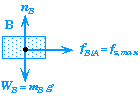
For top block B the normal force is equal to its weight alone. For block A the normal force is the weight of both blocks. The total force with which block A is pressing down on the surface is its weight plus the vertical force that block B pushes down on A - the weight of B.
![]()
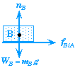
Two situations can arise: block B can either stays put or slips on top of block A. If block B remains stationary relative to A, then it will have the same acceleration as block A, aB= aA. Moreover, the force accelerating B will be the force of static friction. The greater the acceleration, the greater will be the size of the static friction, up to the static limit of fmax = msnB. Note that there is no way to determine the specific value of the static friction from some "static friction" equation - the equation msnB is the maximum value. Static friction is a reaction-force which depends upon the state of acceleration of B and ultimately upon A's acceleration which in turn depends upon the forces applied to A.
When the acceleration of block A (due to Fapp) is too large, the static friction will no longer be able to create a large enough force on B to accelerate it with the same acceleration as A. In this case B will still have an acceleration which results from the kinetic friction acting on B and it represent the maximum acceleration that block B can attain amax. Unlike the static friction the kinetic friction can be calculated from mknB. Since ms> mk, block B's acceleration will be less than that of A, and A will accelerate out from underneath B.
Summarizing the application of Newton's 2nd Law on block B we have,
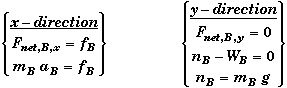
Now we apply these in the two situations in which B is not slipping and slipping. We also include the boundary conditions at the moment B begins to slip, i.e. when aB = amax and aB = aA.
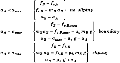
What this example shows is that determining the bottom line equation to solve many problems is not just a case of grabbing the generic equation and plugging values to find an answer.
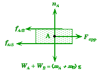
Block A: |
|
No Motion Case:
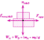
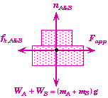
If the applied force Fapp is small enough, then neither block will move. The easiest way to determine the maximum applied force that will cause no-motion is to consider both blocks together as a single system.
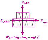
Free-Body Diagram of both blocks as a system
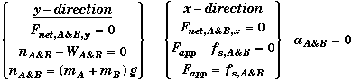
Relevant Equation for system of both Blocks
Note that you can only calculate the static friction using Newtons Second Law. Here we see that the static friction will equal the applied force up to the point when the applied force becomes greater than the maximum static force of friction.
Block B Does Not Slip Case:
When Fapp exceeds the static limit fs,A&B, then the bottom block A will begin to accelerate. If the acceleration produced by Fapp is less than amax, then both blocks will accelerate together. Again it easiest to consider both blocks together as a single system in this circumstance. The y-direction equations are the same as above, only the x-direction equations change.
Note that we can now calculate the frictional force independently from its own equation since it is due to kinetic friction and fk,A&B = mk(mA+mB)g. Moreover, the kinetic frictional force is constant and does not depend upon the magnitude of the acceleration of block A or the applied force Fapp.
Block B Slips on Top of Block A Case:
When A and B have different accelerations then we need to look at how Newton's Laws apply to each block separately.
We have already looked at this for block B. When B is slipping, kinetic friction is the only force acting on B, giving it an acceleration of aB = mkg. Moreover, when B begins to slip, the frictional force it exerts on A will decrease to the fixed value for the kinetic friction, fA/B = mkmBg.
The kinetic friction between block A and the surface, fA/S is still the same, since the force pressing A into the surface is still just the weight of both blocks.

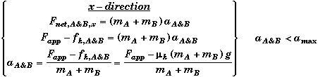
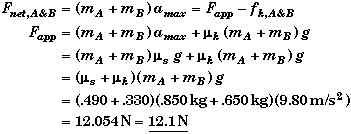
(A) Find the maximum value of Fapp such that aA = 0.
The blocks will not move until the applied force exceeds the maximum static friction limit between block A and the surface. The force that block A exerts on the surface below it is equal to the weight of both blocks not just A's weight alone. Thus the normal force nA&B is equal to the weight of both blocks, (mA+mB)g. (This is easily deduce from applying Newton's Second Law in the vertical direction - see Relevant Physics.) At the maximum value of Fapp the acceleration is still zero the static friction equal the static limit, nmsg. 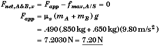 |
|
For any value of the applied force less than 7.20 N the static friction will equal the applied force. Note that for values of the applied force less than 7.20 N this is the only way you can determine the value of the static friction. The static friction is a reaction force and can only be determined using Newton Second Law when it is less than its maximum value, nmsg. This similar to the normal force.
Once the Fapp exceeds 7.20 N then the blocks will begin to move, because the retarding frictional force will drop to a lower value - that associated with the coefficient of kinetic friction.
We can calculate both blocks acceleration at the static limit using the following approximations:
- The Fapp is approximately equal to the value of the static friction limit just found.
- The acting frictional force has dropped to that of kinetic friction.
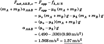
Note that if the static and kinetic coefficients of friction were the same, then the acceleration at the static limit would be zero. This is one reason why mk has to be less than ms.
A reasonable question to ask is "How do I know that block B does not slip initially when A begins to move with the acceleration aA = (ms - mk)g ?" In the relevant physics we found that if aA > ms g , block B would slip. Since ms g > ( ms - mk) g, block B can never slip when the bottom block A just begins to move. This of course depends upon the fact that the coefficients of friction between all surfaces are assumed to be identical. If the coefficient of static friction between B and A were different and small enough, then B could slip when A first begins to accelerate.
(B) Find the maximum acceleration amax of the bottom block A without the top block B slipping, and find the Fapp that will produce this acceleration.
Block B will remain stationary relative to block A - even if A is accelerating - as long as the force needed to accelerate B at the same rate as A does not exceed the static limit of B on A. The maximum acceleration of B (and thus A) is at the static limit on B. 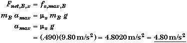 |
|
Surprisingly, amax does not depend upon the mass of either block, but only on the value of the static friction between the top block and the bottom block.
At the moment just before B begins to slip both blocks will have the same acceleration, amax . We can use the system of both blocks to now find the necessary applied force.
As soon as B begins to slip, the net force on A will decrease since the frictional force between A and B will suddenly decrease from the static limit to kinetic value, thereby causing the acceleration of A to increase beyond amax.
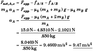
(C) Find the acceleration of block A, aA , and the acceleration of blck B, aB , when Fapp = 15.0 N.
Since Fapp is greater than 12.054 N we know from part B that both blocks are slipping. The acceleration of B is just due to the kinetic friction between it and A.
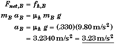
Tis result is independent of the size of applied force once block B begins to slip. This is clear proof that Fapp acts directly on A and not B.
Note that a box in the back of a pickup truck will slide backward for the same reason when the acceleration of the truck become too large. Here the force needed to accelerate the box at the same rate as the truck is larger than the maximum static friction on the box. You more ofen observe the reverse of this when a car brakes to a halt to quickly and the maximum static friction on lose objects is not large enough to keep the objects in place relative to the car and they come sliding forward.
To find aA we use block A's free-body force diagram and apply Newton's Second Law to block A.
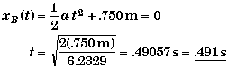
(D) Find t when the end of the blocks are aligned, if Fapp = 15.0 N.
From part C we know the acceleration of each block. Since both blocks start off from rest, the distance they move in time t is,

At the time t the centers of the two blocks will be separated by
Thus,
 Alternately, you could have imagined you were riding along with block A. Then you would see block B accelerate backwards with an acceleration equal to the difference between the acceleration of A and B, aB - aA = -6.2329 m/s2. If you placed the origin at the left end of block A, then initially the left end of block B would be .750 m from the origin.
Linear Static Equilibrium of the Center of Mass:
* The vector sum of all the forces acting on the object must be equal to zero.
* The sum of the horizontal components of all the forces must be equal to zero, and the sum of the vertical components of all the forces must be equal to zero.
* The sum of the components of the forces to the right must be equal to the sum of the components of the forces to the left, and the sum of the components of the forces up must be equal to the sum of the components of the forces down.
Bound Stacked Blocks
Block A weighs 115 N and rest on a rough, horizontal surface and a second block B that weighs 250 N is placed on top of block A. Block B is also attached to the wall by a horizontal cord. A horizontal force is applied to the bottom block to push it out from underneath the block resting on it. To make things simple we assume that the coefficient of friction (both kinetic and static) between all surfaces is .420. |
|
(A) |
What is the minimum force that one needs to exert on block A so that block A will move out from underneath block B ? |
(B) |
What is the tension in the cord attached to block B if block A is pushed out from underneath block B ? Does the tension depend upon the force pushing A ? |
(C) |
If block A is pushed to the right by a 317 N horizontal force, what is the acceleration of block A ? |
Sketch and Process:
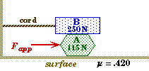
Block B remains stationary while block A is accelerated out from underneath block B. There is friction between the two blocks and block A and the surface.
Givens and Labels
WA |
= 115 N |
|
(Weight of block A) |
WB |
= 250 N |
|
(Weight of block B) |
FA |
= 317 N |
|
(Force on block A) |
m |
= .420 |
|
(Coefficient of friction between all surfaces) |
aA |
= ? |
|
(Acceleration of block A) |
aB |
= 0 |
|
(Acceleration of block B) |
T |
= ? |
|
(Tension in the cord connected to B) |
nA |
=? |
|
(Normal force acting on block A) |
nB |
= ? |
|
(Normal force acting on block B) |
fA/S |
= ? |
|
(Force of friction between A and the Surface) |
fB/A |
= ? |
|
(Force of friction between B and A) |
Relevant Physics:
The key to solving this problem is to consider each block as an independent system for which Newton 2nd Law applies. Additionally, one must identify the frictional forces and normal forces acting on each body separately by drawing a free-body force diagram for each block.
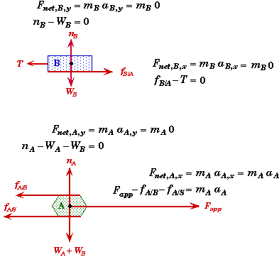
From Newton's 3rd Law the frictional force on B due to A, fB/A, and the frictional force on A due B, fA/B, are equal an opposite forces. For clarity, we assume that the symbols we use for the frictional forces represent their positive numerical values. We take their direction into account by placing a + or - sign in front of them when we used them in an equation.
Observe that we do not have Fapp acting on block B since its point of application in on A not B. The applied force Fapp does effect B but is does not directly act on B. It effects B through the frictional force between A and B.
We did not draw the frictional forces through the center of mass of the blocks in order to more clearly indicate the source of those frictional forces. Also note that magnitude of Fapp must be bigger than the sum of fA/B and fA/S for block A to move as we have sketched it.
(A) Find Fapp,min such that block A starts moving.
Frictional Forces:
There are two frictional forces acting to retard the motion of block A. These come from the two surfaces in contact with A. Before A moves, these frictional forces are due to the static friction between the surfaces. Block A will begin to accelerate when the static frictional forces reach their maximum values. Since the coefficient of kinetic and static friction are the same, then the maximum frictional forces are the same as the kinetic frictional forces.
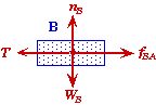 Block B:
Since nether block moves upwards or downwards, the net force in the y-direction must be zero on each block. Thus the normal force must be equal to the force pressing the surfaces together. For block B, the force pressing block B down onto A is just the weight of B alone since it is on top.
![]()
Block A:
For block A, the normal force pressing A against the surface is the weight of both blocks not just block A alone.
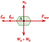
![]()
Just before A begins to move its acceleration will be zero and Fapp = Fapp,min.
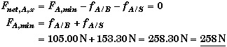
Note that the static friction between A and B will be zero for an applied force less than 153.3 N. Up to this point the static friction between A and the surface will be large enough to cancel any applied force less than 153.3 N. This also means that the tension in the cord will be zero until Fapp > 153.3 N. The tension will then increase (as Fapp is increased beyond 153.3 N) up to the moment when A breaks lose and begins to move. The applied force will then equal to 258.3 N
(B) Find T in the cord when block A is moving.
As block A slided underneath block B, block B remains stationary. Thus the net force on B must be zero. Applying Newton's 2nd Law horizontally to the block B alone we get
![]()
The magnitude of frictional force acting on block B due to its contact with A, fA/B , is the same as the frictional force on A due to B, fB/A , which we found in part A.
Since the model we are using to calculate the kinetic frictional forces is independent of the speed of the object, this means that (for small velocities) the tension in the cord is independent of how fast block A is pushed out from underneath block B.
(C) Find aA of block A when Fapp = 317 N
Since 317 N is greater than 258.3 N, the minimum force needed to move the bottom block, we know that block A will have a non-zero acceleration, otherwise its acceleration would be zero if the applied force were less than 258.3 N. Applying Newton's 2nd Law horizontally to block A we get

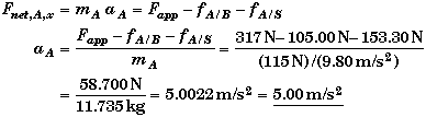
Observe that if Fapp were less than 258.3 N then we would have obtained a negative value for the acceleration which would be impossible. Getting a negative acceleration would indicate that either the problem was bogus or that we made some error. The most likely source of error in this type of problem arises from incorrect assumptions about the forces acting on the blocks when setting up the problem.
Torque Due to the Weight of an Object:
* The torque on a solid body (about any axis) produced by the object's own weight can be calculated as if all the object's mass were located at the center of mass of the object. Here the lever arm is the distance between the pivot point and the center of mass.
* Since freely rotating systems revolve about their center of mass, the weight of an object cannot create any torque on the object when it is rotating freely.
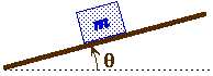 Physics on an Incline Plane
A block of mass m rests on a surface that is inclined at an angle q relative to the horizon.
Frame of Reference:
- The key to solving problems involving an incline plane is to resolve the force-vectors acting on the block (or blocks) into components that are either parallel or perpendicular to the surface of the incline plane. Since the block is assumed not leave the incline plane's surface all the motion will take place along the incline plane - the block's acceleration perpendicular to the plane is always zero as long as it is in contact with the incline plane.
- This is equivalent to rotating a normal coordinate system by an angle q.
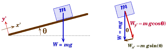
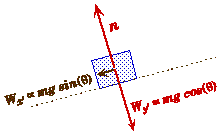
Component of gravity pushing the block down the incline plane.
Wx' = mg sin(q)
Component of gravity pushing the block against the incline plane.
Wy' = mg cos(q)
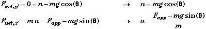
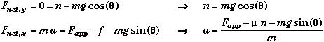
- As long as a block stays in contact with the surface of the incline plane, the sum of the forces on that block that are perpendicular to the incline plane will be equal to zero and the motion of the block will be along the surface of the incline plane. Newton's Second Law then gives the general relation that is always true for this type of problem.
![]()
Frictionless Incline Plane with no Applied Force:
Free Body Force Diagram
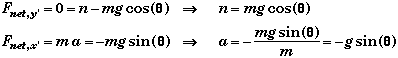
- In this case the block would accelerate down the incline plane. In fact if the incline plane was vertical so that q = 90o then a = -g sin(90o) = -g, i.e. then problem would go over to that of a simple free-fall problem.
Frictionless Incline Plane with Parallel Applied Force:
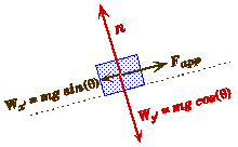
Free Body Force Diagram
- Here the block could accelerate up or down the incline plane depending upon the size of the applied force.
Incline Plane with Parallel Applied Force and Friction:
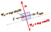
Free Body Force Diagram
- If the applied force is not parallel to the surface then it will need to be split into two components, one parallel to the surface and the other perpendicular to the surface. Note that this will cause the frictional force to change since the normal force will be increased or decreased.
- The direction of motion depends not only upon the applied force, the weight of the block, and also on the direction of the force of friction.
Centripetal Force and Acceleration:
Centripetal Acceleration:
- In order for an object to execute circular motion - even at a constant speed - the object must be accelerating towards the center of rotation. This acceleration is called the centripetal or radial acceleration and has a magnitude of
![]()
ac |
= Centripetal acceleration |
SI: m/s2 |
vT |
= Tangential velocity or speed |
SI: m/s |
r |
= Radius of object's path |
SI: m |
w |
= Angular velocity |
SI: rad/s |
Centripetal Force:
- The radial force needed to create this acceleration is call the centripetal force. It is directed towards the center of rotation and has a magnitude of
![]()
- For any object undergoing uniform circular motion, the net force towards the center of rotation must have a value equal the centripetal force.
- In a frame of reference rotating with an angular velocity w (omega), the object will be at rest, yet seem to experience a force acting upon it radially outwards equal to m w2r. This is because a rotating frame is a non-inertial frame of reference, i.e. the frame does not move at a constant speed in a straight line, and consequently Newton's First Law does not apply.
- It is sometimes useful to move into a frame that is rotating with the system. In this rotating frame, the centripetal force is replaced with a force of the same magnitude acting outwards, which is called the centrifugal force. ("Centrifugal" means "fleeing from the center.") In solving a problem in the rotating frame, the centrifugal force can be treated as though it were another physical force acting on the object with a magnitude m w2r (the same magnitude as the centripetal force) directed radially outwards. Most physicists would advise against doing this, because the centrifugal force is not a real force. I still find it useful in visualizing a problem.
Dynamics Problem-Solving:
Summary
- Choose a system and/or subsystems on which to concentrate.
- Determine the type of forces acting on the system
- Draw a free-body force diagram of the system.
- Apply Newton's 2nd Second Law to the system.
Which object or group of objects will I take to be a system?
* Any single body can be considered to be a system to which Newton's 2nd Law can be applied.
* When a problem has several objects connected together somehow, each object could still be considered to be a separate system. In addition, any pair of objects (or all the objects taken together) could also be considered to be a system.
* To make it clear which system you have chosen, sketch the object or group of objects by themselves, isolated from their surroundings. This is part of constructing a free-body diagram.
What are all the forces acting on the system that I have chosen ?
* Decide which forces are acting on the system and which forces are not acting on the system. This is the most difficult part of the process, because you cannot really see force. You can only see the result of the force's action.
* Only those forces that make direct contact with the system will expressly act on the system. It takes some experience to know what forces are acting directly on the system and what forces have an effect on the system but are not acting directly on the system.
* The net force Fnet is not a force acting on the system. It is the resulting force due to the action of all the other forces. You could replace the action of all the forces with the net force. However, it is not one of the forces which acts on the system, it is representative of all of them. Likewise, the quantity ma is not a force acting on the system, it is the magnitude of the net force, Fnet = ma.
* Sketch all the forces acting on the system, along with their directions, to construct a free-body force diagram.
* Any force that the system exerts on its surroundings is not a force that you should include. However, by Newton's 3rd Law there is a reaction force that will be acting on the system that you should include.
* An object's velocity-vector is not a force. It surely took a force to give the object a velocity, but once that force is no longer acting on the system it does not somehow transfer its "action" to the object's velocity. Newton's First Law shows that an object does not need any force to keep it moving at a constant speed.
How do I apply Newton's Laws to solve the problem ?
* Choose a frame of reference and sketch its origin on your free-body diagram. It is useful to try to guess which direction the system will move and make that direction the positive axis of one of your coordinate axis.
* Resolve the force-vectors into components to determine the net force along each coordinate direction.
* Write down Newton's 2nd Law for each coordinate direction. For the horizontal-vertical coordinate system, this will have the form,
![]()
* If you have not already done so, express the terms in these Second Law equations using the personal labels you have chosen for the problem.
* Be consistent with the signs you place in front of the forces. Make sure the actual direction of the action of any forces you write down in Newton's 2nd Law equations is indicated correctly by the sign you use when you write them down. The hardest force to express correctly is the direction of the force of friction.
* Replace any force terms in these Second Law equations with the equations associated with each particular type of force. In particular, any spring force can be replaced with Hooke's Law, Fs= -k x, kinetic friction can be replaced with f = mkn, and the force of gravity can be replaced with W = m g. Rather than replacing them, you can also just write them down along with the Second Law equations.
* Examine the resulting equations to determine what quantities you know and what quantities you do not know. It can be helpful to re-read the problem at this point if you have any doubts. Having already explicitly considered what information is given and what is requested could make this part a snap.
* At this point you may be able to solve the resulting equations for the requested unknowns. If not, reconsider each of the steps you have taken to see if anything is missing or inconsistent with what you know about the behavior of the type of system described in the problem. Check your steps with your intuitive expectations and the facts you are certain of to that point.
* When you do finally get an answer, make sure that it is reasonable with what you expect for this type of process. For example, does the answer indicate that the system is moving in the direction you anticipated ? Are any of the forces you found unreasonably large or small, or in the wrong direction. ?
Double Pulley Problem
A massless, frictionless pulley is attached to the top of block A which has a mass of 5.00 kg. A light cord which is attached to the ceiling drops down, passes through this pulley, and back up through a second massless, frictionless pulley that is attached to the edge of a table. The cord bends over top of this second pulley and travels horizontally to a 2.50 kg block B which rests on the frictionless surface of the table top. |
|
(A) |
When block A is released, how does the acceleration of block A compare with the acceleration of block B ? |
(B) |
What is the acceleration of the two blocks ? |
(C) |
What is the tension T in the cord ? |
(D) |
Can the tension T in the cord ever be equal to the weight of B ? (of A ?) |
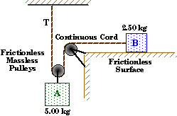 Sketch and Process:
Two connected blocks are accelerated by different processes. One block is accelerated by gravity with its motion being retarded by the tension in the cord. The other block is accelerated by the tension in the cord alone.
Reference Frame:
We choose down as positive for block A, since that will be its direction of motion. This means that aA will be positive also.
Because of the way we sketched the problem, we choose left to be positive for block B so that its acceleration will also be positive.
We start the clock when block A is released.
Givens and Labels:
mA |
= 5.00 kg |
(Mass of block A .) |
mB |
= 2.50 kg |
(Mass of block B.) |
aA |
= ? |
(Acceleration of block A.) |
aB |
= ? |
(Acceleration of block B.) |
Fnet,A |
= ? |
(Net force on block A.) |
Fnet,B |
= ? |
(Net force on block B.) |
Each block starts from rest.
Relevant Physics:
Since all the forces acting on the blocks are constant, so will the acceleration of both blocks also be constant. This means that the kinematic equation for constant acceleration can be applied to both blocks.
Newton's Second Law can be applied to each block separately.
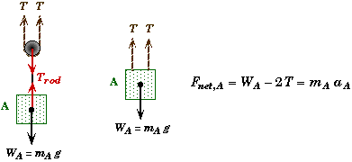
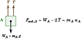
System of Block A:
Block A has two forces acting on it, gravity and the tension in the rod connecting it to the pulley. We are only interested in the tension in the cord and not the connector-rod's tension. Looking at the pulley as yet another system we can see by Newton's Third Law that the connector-rod's tension is equal to twice that of the tension in the cord, since there are two strands supporting the pulley. The free-body force diagram would look something like,
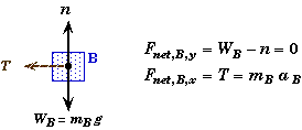
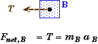
System of Block B:
There are three forces acting on block B: gravity, the normal force, and the tension in the rope. Applying Newton's Second Law to the free-body diagram of B we get,
We cannot construct a system that consists of both blocks, since the blocks do not have the same acceleration. Part A shows that the acceleration of A will be half that of the acceleration of B.
(A) What equation connects the acceleration of the two blocks ?
Since A is supported by two strands of the cord, the distance moved by A will be 1/2 the distance moved by B in the same amount of time. Their comparative accelerations are given by the equations for constant acceleration.
![]()
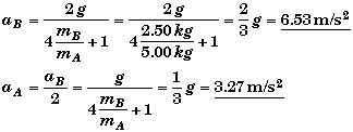
(B) Find aA and aB.
Applying Newton's Second Law to each block separately we obtain two equations with three unknowns.
Combining these two equations along with the relationship between the two accelerations found in A, we can eliminate the tension T and find the acceleration of either block. We will eliminate aA to find aB first.
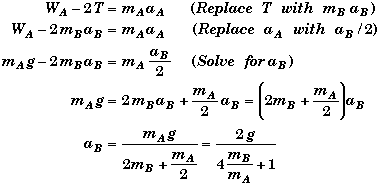
Thus,
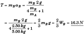
(C) Find the tension in the cord, T.
Since we already know aB from part A, we can substitute it into T = maB and find T. Otherwise, the following solution works well:
(D) Can T = WB ?
Assume that T = WB and see what this implies about the relationship between the masses of the two blocks. We will need to use the expression we found for T in part C.
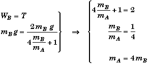 YES!
YES!
Thus if block A is four times as massive as block B, then the tension in the cord will be equal to the weight of B.
Can T = WA ?
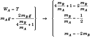 NO!
NO!
Since there is no way to have a negative mass, it would be impossible. The maximum tension would occur when block B is held in place. Then the tension would only be 1/2 of block A's weight, since there are two strands of the cord supporting the weight of A.
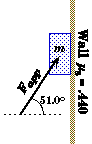
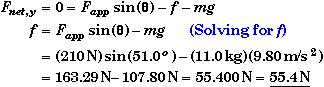
A 11.0 kg block is pressed against a vertical wall by an applied force, Fapp that makes an angle of 51.0o with the horizontal. The coefficient of static friction between the block and the surface of the wall is .440. |
|
(A) |
If the wall were frictionless, what magnitude of force (at 51.0o) would be needed to keep the block from slipping down the wall ? |
(B) |
With what force does the block press against the wall if the applied force is 210 N ? |
(C) |
What is the magnitude and direction of the force of static friction if the applied force is 210 N ? |
(D) |
Over what range of the magnitudes of the applied force will the block not slip down the wall ? In particular, what are the maximum and minimum values of the applied force that would keep the block motionless ? |
If the applied force is fixed at 210 N, what are the maximum and minimum angles that this force can be applied and still have the block not slip ? |
|
Sketch and Process:
An object is kept from slipping down a vertical wall by an applied force and the resulting frictional force.
Reference Frame:
Since the block is stationary, any frame will do.
We choose the horizontal and vertical directions in which to resolve vector components.
Givens and Labels:
m |
= 11.0 kg |
(Mass of the block) |
ms |
= .440 |
(Coefficient of Static Friction) |
q |
= 51.0o |
(Angle of the Applied Force from horizontal) |
Fapp |
= ? |
(Magnitude of the Applied Force) |
|
= 210 N |
(Magnitude of the Applied Force in Parts B, C, and E) |
Relevant Physics:
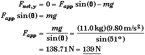
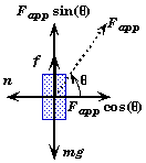
![]() Since the block does not move the net force on the block must be equal to zero.
Since the block does not move the net force on the block must be equal to zero.
The keys to solving this problem are:
- Identifying ALL the forces acting on the block (i.e. drawing a free body force diagram)
- resolving those force vectors into horizontal and vertical components.
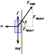
![]()
Newton 2nd Law becomes
![]()
The frictional force is due to static friction. Note that although the static frictional force f is always vertical in this problem, the friction's direction is not necessarily always upwards as we have drawn it. It could be down in some cases. This would happen if the vertical component of the applied force, Fapp sin(q), is greater than the weight of the block, mg. In those cases, the block would slide up the wall if there were no friction.
Since friction always opposes the direction of motion, the friction will be down if Fapp sin(q) > mg, and it will be up if Fapp sin(q) < mg.
The maximum value of the static friction can found from,
![]()
For Fapp = 210 N and q = 51.0o, (in parts B, C, and E)
![]()
This is the maximum force that friction can produce to resist the block's motion down the wall when Fapp sin(q) < mg. It is also the maximum force of friction that will resist the block's motion up the wall if the vertical component of the applied force is greater than the weight of the block, i.e., Fapp sin(q) > mg.
For the block not to slip,
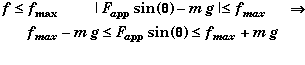
This is a fairly complex trigonometric function since fmax is itself a function of Fapp and q,
![]()

(A) Find Fapp when ms = 0 and the block does not move.
Appling Newton's Second Law to the free-body force diagram, when there is no friction we find,
Observe that if Fapp > 139 N then the block would tend to slide up the wall unless there is friction. Likewise, if Fapp < 139 N then the block would tend to slide down the wall unless there is friction.
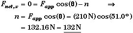
 (B) Find n when Fapp = 210 N.
Whether or not there is any friction, the normal force pressing the block to the wall only depends upon the horizontal component of the applied force pushing the block against the wall. The normal force is not affected by the weight of the block, since the direction of the weight and the direction of the normal force are at 90o to each other. This problem shows that the normal force on an object is not always equal to the object's weight, as it is many problems.
Applying Newton's Second Law in the horizontal direction,
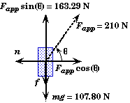 (C) Find the force of friction f when Fapp = 210 N.
We know from part A that the block would slide up the wall if there were no friction and Fapp sin(q) > mg, or more specifically if Fapp > 139 N
Since friction opposes the motion, the force of static friction will be down in this case. (The force of friction would be up if Fapp < 139 N.) Letting f represent the magnitude of the frictional force, the vertical component of Newton’s Second Law becomes,
This is a some what surprising result since at first glance one might expect the force of friction to be up and not down. The static friction can be made to up if Fapp < 139 N.
(D) Find the range of Fapp where the net force on the block is zero.
 The maximum value of the static friction occurs when
![]()
From Newton's Second Law applied horizontally to the free-body force diagram we know (from part B)
![]()
so that
![]()
Since we do not know Fapp yet, we cannot calculate fmax.
From Newton's Second Law applied vertically (see part C) we see that
![]()
Replace fmax with its functional relation to Fapp and solve for Fapp,
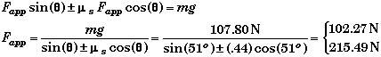
Thus the minimum force needed to keep the block from slipping down the wall is 102 N, with friction supplying the additional force up to support the weight of the block. In this case f = ms Fapp cos(q) = 28.3 N upwards.
The maximum force that can be applied before the block begins to slide up the wall is 215 N. In this case f = ms Fapp cos(q) = 59.7 N downwards.
(E) Find qmin and qmax when Fapp = 210 N.
This problem is nearly the same as the last question, part D, in that the conditions for non-slip are the same
![]()
Here q is the unknown and Fapp is known.
You cannot use algebra to solve this equation for q; it is a trigonometric equation of q.
Calculator Solve Mode:
The first way is to enter the above equation and the values of the known quantities into a calculator, and to then use the solve mode to find q. This gives qmin equal to 4.28o, and qmax equal to 51.8o to 3 significant figures.
Note that you could also use this method to find Fapp in the last question. Here you would have specified the angle and then used the solve mode to find Fapp.
Graphical Solution:
The second method would be use a calculator to plot the following two functions as a function of q and see where they cross each other.
|
We have chosen these two functions since they have more physical meaning. The first function represents the net force (in the vertical direction) on the block in the absence of friction, and the second function gives the maximum and minimum values of the force of static friction. The graph of the two functions shows
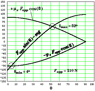
You could also plot the function ![]()
![]() and see where it is equal to mg .
and see where it is equal to mg .
Trigonometric Solution:
One way to produce an analytical solution is to compare the structure of the following trigonometric identity and the equation for non-slip,
![]()
If we construct a triangle with sides equal to Fapp and ms Fapp, then
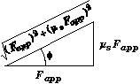
We can rewrite the non-slip equation as
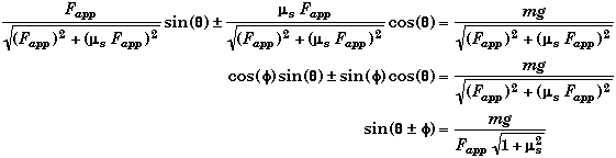
Solving for q,
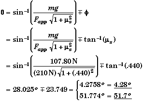
This what you call an elegant solution. It would be useful if you needed to use the values for q in some other expression.
Source: http://physics.mtsac.edu/4A/4A%20Text/Forces.doc
Web site link : http://physics.mtsac.edu/
Author : not indicated on the source document of the above text
If you are the author of the text above and you not agree to share your knowledge for teaching, research, scholarship (for fair use as indicated in the United States copyrigh low) please send us an e-mail and we will remove your text quickly.
Force notes
Force notes
Force notes
This is the right place where find the answers to your questions like :
Who ? What ? When ? Where ? Why ? Which ? How ? What does Force notes mean ? Which is the meaning of Force notes?
Force notes physics notes
Alanpedia.com from 1998 year by year new sites and innovations
Main page - Disclaimer - Contact us