Geometric optics
Geometric optics
The following text is used only for teaching, research, scholarship, educational use and informative purpose following the fair use principles.
We thank the authors of the texts and the source web site that give us the opportunity to share their knowledge
Physics
Geometric optics
AP Physics – Geometric Optics
 We’ll start off our exploration of optics with the topic of mirrors. The type of mirror you are most familiar with is called a plane mirror. Your first thought is probably, “What do we care about mirrors on airplanes for?” Well, not that kind of plane mirror. Although this stuff would certainly apply to mirrors on planes. Anyway, plane mirrors are flat and have a metal surface. Some times they are made of metal – the first mirrors found by archeologists were made of polished brass. Jason (owner of the good ship Argo) used a polished metal shield as a mirror when he chopped off the head of the Gorgon Medusa (he had to use a mirror because if you look at a Gorgon, they like turn you into stone). Modern mirrors are made of glass or clear plastic and have a thin, very smooth layer of metal on one side. Nowadays the metal is usually aluminum but it mostly used to be silver, so the metal surface is called the silvered surface. Most mirrors have the silvering on the far side under glass so it won’t get scratched. Mirrors for very precise applications (like in projection TV’s) are front silvered.
Plane mirrors form images. When you look into the mirror you see all sorts of wondrous things.
Remember that the only way you see anything is for light rays to enter your eyes. When you look at a mirror, everything that you see in the mirror is being reflected off the surface of the mirror. Our eyes, primitive as they are, do not understand that light rays can be reflected. Our eye/brain system is convinced that light rays always travel in straight lines. When we look into a mirror, light rays seem to be coming from objects that are on the other side of the mirror. In reality the objects are on the same side of the mirror as we are and the light rays are reflected into our eyes. The drawing below shows how an image of an arrow is formed. Two rays are shown coming off the object (the arrow). A ray from the top and a ray from the bottom. The ray from the top reflects off the mirror into our eye and the ray from the bottom does the same. Our brain “ray traces” the reflected rays back behind the mirror. We call these the back rays. Your eye and brain are back ray tracing.
The image is formed in our brain on the opposite side of the mirror. It is the same size as the object and the same distance from the mirror as the object.
The image is called a virtual image. Think of virtual image as meaning that the image is made by phantom rays. No real light rays form the virtual image.
Plane mirrors form images that are erect, non magnified, and virtual.
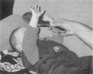
Here is a baby, the baby does not understand about virtual images and is foolishly trying to grab its image (which it thinks is behind the mirror) with its free hand.
Spherical Mirrors: Spherical mirrors produce a very different type of image. So first things first, what is a spherical mirror?
A spherical mirror has a curved surface. The surface has a constant radius of curvature. You could think of it as sort of like a circular part of a mirror that is a true sphere. Sort of a cookie cut out of the thing. The little round cookie has a curved surface. So the mirrored surface is part of sphere.
There are two types of spherical mirrors, convex mirrors and concave mirrors. The type a mirror depends on where the silvering is placed.
 |
On the drawing above, you can see that on a convex mirror, the silvering is on the side that bulges out. A concave mirror has the silvering on the side that caves in. In fact the cute little way to remember which is which is that a “concave mirror makes a cave” or some such nonsense.
Here is a drawing showing the geometry of a concave mirror.
C is the center of curvature. Its distance from the center of the mirror is equal to the radius of curvature R for the mirror.
The principle axis is a line that goes through the center of curvature to the center of the mirror.
f is the principle focus. It is also called the focal point or sometimes simply the focus.
The focal length is the distance from the principle focus to the center of the mirror. It is equal to one half of the radius.
![]()
Rules For Ray Reflection: The reflection of light rays that enter spherical concave mirrors follow certain specific rules. Here followith those very rules.
- Rays that enter the mirror parallel to the principle axis are reflected off the mirror through the principle focus.
- Rays that pass through (or appear to originate from) the principle focus are reflected parallel to the principle axis.
- Rays that pass through (or appear to originate from) the center of curvature enter the mirror and are reflected back through the center of curvature.
Ray 1 -- Comes in parallel to the principal axis, is reflected through f.
Ray 2 -- Enters by passing through the focal point, is reflected off the mirror parallel to the principle axis.
Ray 3 -- Goes through center of curvature, is reflected off the mirror through the center of curvature. It retraces itself.
Image Formation: Let’s look at a typical image formed by a concave spherical mirror.
 The object is located between the center of curvature and the principle focus.
The object has a humungeous number of rays reflecting off it in all directions. We are only interested in the rays that follow our rules.
So the first ray we look at is one coming off the top of the object parallel to the principle axis. It will be reflected off the mirror through the focal point.
 The next ray that we draw is the one that goes through the principle focus. It is reflected off the mirror parallel to the principle axis.
 These two rays fix the image, the top of the object (the arrowhead) is located where the two rays intersect. The bottom of the object is fixed by the principle axis. Rays from the principle axis that travel through the focal point are parallel to the principle axis, they also appear to originate from the center of curvature, so the base of the object stays attached to the principle axis.
This is a real image because it is made up of real light rays that actually intersect each other. It is inverted. Also note that for this specific example that the distance from the image to the mirror center is greater than the object distance. Also the image is magnified.
Be sure to remind the Physics Kahuna to show you his real image demonstrations.
 As the object is moved about in front of the mirror, the image size and image distance will vary. The image can be smaller or larger than the object.
It is interesting to look at what happens when the object is placed at the focal point:
Note that the two rays are parallel. They will never intersect, so there can be no image. Thus no image is formed of an object that is at the principle focus of the concave mirror.
 What happens when the object is placed inside the principle focus? Let’s look at the rays and see what happens.
When we trace out the three rays, they don’t cross in front of the mirror. So what is going on?
Did you see it? Yes, your brain appraises the situation and says to itself, “Hey these rays all look like they’re coming from behind the mirror!” Your brain does a bit of back ray tracing is what happens. So we end up with a virtual image that is erect and magnified.
People buy these mirrors so that they can get a virtual image of their faces in the thing. The manufacturers call them makeup mirrors (if the market is women) or shaving mirrors (if the market is men).
Concave mirrors are also known as converging mirrors because reflected light rays can converge to form real images.
Convex Mirror Images: Convex mirrors also form images. But the image that forms is always virtual and smaller. Convex mirrors are also known as diverging mirrors because the reflected rays always diverge and can never form a real image.
Here we see a convex mirror with an object placed in front of it. The main difference here is that the principle focus is on the opposite side of the mirror from the object.
The rules for the rays are pretty much the same, but there are a couple of little differences. Notice also that we don’t really care about the center of curvature.
Rays that are parallel to the principle axis are reflected as if they originated from the principle focus.  The ray is reflected off the mirror as if it had started out at the principle focus.
Rays that look as if they are going to go through the principle focus are reflected off the mirror parallel to the principle axis. Let’s look at this ray.
 Note that the rays will never cross in front of the mirror. So, the old brain has to go in and do some major back ray tracing.
 You get something that looks like this:
For a convex mirror, the image will always be virtual and will always be smaller than the object.
Convex mirrors are used to give a big field of view. Because objects in front of the mirror are smaller as an image, you get a bigger view in the mirror. So the mirrors are used on cars and trucks as rear view mirrors. They are also used in stores as security mirrors. A couple of mirrors mounted in the corners give a view of the entire interior of a store.
Lenses: Enough already on mirrors. Let’s talk about lenses. You know what they are – you may have a pair of them in your eyeglasses, or do you wear contact lenses?
Lenses refract light in a sort of organized way. The type of lenses that we’ll be looking at are called double spherical lenses – both sides of the lens have the same radius of curvature. There are two types of these lenses: convex lenses and concave lenses. Concave lenses cave inward and convex lenses bulge outward.
Convex lenses are also known as converging lenses because the refracted rays that pass through can converge. Convex lenses can form real or virtual images.
Concave lenses are called diverging lenses because the light rays always diverge. Concave lenses can only form virtual images.
Lens Stuff: Here is the geometry of the double convex lens.
Q is the center of the lens, f and f’ are the focal points on either side of the lens. Also note that lens has a principle axis.
Here are the rules for image formation:
- Rays that are parallel to the principle axis are refracted through the focal point on the opposite side of the lens.
- Rays the travel through the center of the lens are not refracted and travel in a straight line.
- Rays that travel through the focal point before they reach the lens are refracted out of the lens parallel to the principle axis.
Note: the Physics Kahuna likes to draw a vertical line on the lens, that is a line through the center of the thing. No doubt it will be clear how this vertical line is used.
Ray 1 is the parallel ray that is refracted through focal point on the opposite side of the lens.
Ray 2 is the ray that goes through the center of the lens.
Ray 3 is the ray that goes through the focal point and is then refracted parallel to the principle axis.
The image is formed where the rays intersect. Clearly you can see that this will be a real image.
Converging lenses form real images, they can also form virtual images as well. This is what happens when you use one as a magnifying glass.
Here is a virtual image formed by a converging lens. Notice that the object is inside the focal point. When an object is placed at the focal point no image forms. This is shown in the next drawing. This is because all the rays are refracted in such a way that they are parallel to one another. They never cross, so they form no image.
What about a diverging lens? Let’s look at how diverging lenses form images. Keep in mind that a diverging lens always produces a virtual image.
- The parallel ray is refracted as if it had started out at the focal point on the same side of the lens as it is.
- The ray that goes through the center of the lens is not refracted.
The rays look like this:
Notice that the rays all diverge. This means that you have to do the old back ray tracing thing to find the virtual image.
You should be prepared to use ray tracing to locate images for spherical mirrors and lenses.
Multiple Lens Deals: Many instruments that use lenses use several of them in series with one another - telescopes, microscopes, camera lenses, film projectors, etc. The way this works is that the first lens forms an image of an object. This image serves as the object for the next lens and so on.
Here is a typical simple set up. There are two lenses and a single object.
First we find the image formed by the first lens.
The first image will then act as an object to the second lens, which will form a final image.
Thin Lens Equation: The relationship between the image distance and the object distance is given by the thin lens equation.

sois theobject distance, si is the image distance, and f is the focal length for the lens.
Lens sign conventions:
so - Positive if object is in front of the lens.
so - Negative if the object is behind the lens.
si - Positive if the image is behind the lens.
si - Negative if the image is in front of the lens.
f is positive for a converging lens.
- A lens has a focal length of 25 cm. An object is placed 32 cm from the lens. What is the object distance?


Magnification: One of the reasons that lenses are used is that they can provide some magnification – make something look bigger.
If you divide the size of the image by the size of the object you get a number that represents the magnification. If the image is 10 cm tall and the object is 5 cm tall then the magnification is two.
The magnification is given by:

M is the magnification, hi is the image height, ho is the object height, si is the image distance, and so is the object distance.
- A double convex thin lens has a focal length of 36.0 cm. A 2.30 cm tall object is placed 12.0 cm from the lens, find (a) the type of image, (b) the image distance, (c) the magnification, (d) the image height.
- Virtual Image. We know this because the object distance is less than the focal length.
(c)  Note: no units for magnification. Also the Physics Kahuna dropped the negative sign. It just tells us that it is a virtual image.
(d) ![]()
- We have us a two lens system. The focal length for the 1st lens is 10.0 cm, the focal length of the second lens is 20.0 cm. (a) Find the final image distance. (b) find the magnification of the final lens.
(a) 


The image is 14.0 cm from the first lens. Since the second lens is 22.0 cm from the first lens, the distance from the first image to the second lens, which will be its object distance, is the difference between the two distances:
![]()
Now we can find the image distance for the final image formed by the second lens:

- Finding the magnification.

Changes in the Lens: What happens to the focal length if the radius of curvature for a lens is changed? What happens if the index of refraction for the mirror is changed? What happens if the lens is immersed into a different medium that has a different index of refraction than does air?
The basic thing to think of is this: what happens to the angle of refraction? Anything that increases the angle of refraction will produce a smaller focal length as the light is bent a greater amount.
First let’s look at changes to the radius of curvature, R. In general, this is what happens. As R increases, the focal length increases. Thick fat lenses (which have a small radius of curvature) have a small focal length. Thin lenses (which have a large radius of curvature) have a longer wavelength. The bigger the radius, the bigger the amount of refraction, the smaller the focal length.
If the index of refraction is changed? If the index of refraction increases the focal length decreases. I f the index of refraction decreases the focal length increases. This is because the light is bent more with a larger index of refraction.
Source : http://teachers2.wcs.edu/high/bhs/mikek/AP%20Physics%20Course%20Notes/Optics/2%20-%20Optics%20.doc
Web site link: http://teachers2.wcs.edu/
Author : not indicated on the source document of the above text
Geometric optics
Geometric optics
Geometric optics
This is the right place where find the answers to your questions like :
Who ? What ? When ? Where ? Why ? Which ? How ? What does Geometric optics mean ? Which is the meaning of Geometric optics?
Geometric optics
Alanpedia.com from 1998 year by year new sites and innovations
Main page - Disclaimer - Contact us