Resistance
Resistance
The following text is used only for teaching, research, scholarship, educational use and informative purpose following the fair use principles.
We thank the authors of the texts and the source web site that give us the opportunity to share their knowledge
Physics
Resistance
The resistance of a conductor is the ratio of the potential difference across it to the current flowing through it.
![]()
Mathematically:
The unit of resistance is the Ohm
Symbol is Ω
Ohm’s Law* states that the current flowing through a conductor is directly proportional to the potential difference across it, assuming constant temperature.
Resistors in series and in parallel
Resistors in Series*
RTotal = R1 + R2
![]()
Derivation:
For resistors in series VTotal = V1 + V2
But V = IR (Ohm’s Law)
Þ I RTotal = I R1 + I R2 (We can now cancel the I’s because the current is the same for resistors in series)
Þ RTotal = R1 + R2
Resistors in Parallel*
![]()
Derivation:
For resistors in parallel ITotal = I1 + I2
But I = V/R (Ohm’s Law)
Þ V/RT = V/R1 + V/R2 (But we can cancel the V’s because the
voltage is the same for resistors in parallel)
Þ 1/RTotal = 1/R1 + 1/R2
Resistivity*
Resistivity is defined as the resistance of a cube of material of side one metre.
or
Resistivity is defined as the resistance of a material of unit length and unit cross sectional area.
The symbol for resistivity is r (pronounced “rho”).
We have come across r twice already in the course – can you remember where?)
The unit of resistivity is the Ωm (can you see why by looking at the formula below?)
![]()
Formula for resistivity: *
Look over Worked Problems 6, 7, 8, page 267. Then try Questions 1 – 8, page 269.
To do these you should revise how to convert from millimetres square to metres square.
See the diagram on page 6 for a reminder.
Measuring resistance using a Wheatstone Bridge*
 A Wheatstone Bridge can be used to find the resistance of an unknown resistor.
The values of the four resistors are arranged – by trial and error – so that no current flows in the galvanometer.
![]()
It can be shown that the relationship between the resistors is
Therefore knowing the values of any three resistors allows us to calculate the fourth.
When using this formula make sure that the resistors are arranged as shown.
Now try Questions 1, 2, 3, page 271 and Exam Question: Page 23, No. 8
Uses of a Wheatstone Bridge
Remember that the bridge above was balanced to begin with, so no current flows through the galvanometer.
Now if the temperature of one of resistors is changed for any reason, current will flow through the galvanometer.
This current can be used to activate a second circuit such as a heater or an alarm.
Examples
- Temperature Control
- A Fail-Safe Device
The metre bridge
This is similar in principle to the Wheatstone bridge, except two of the resistors are replaced by a single strip of uniform-resistance wire, and because resistance is proportional to length the balance point can be reached by simply sliding the contact wire along this lower uniform-resistance wire.
![]()
Example: 2007 No. 9
A metre bridge was used to measure the resistance of a sample of nichrome wire.
The diagram indicates the readings taken when the metre bridge was balanced.
Calculate the resistance of the nichrome wire
![]() Þ
Þ ![]() Þ R = 7.86 Ω
Þ R = 7.86 Ω
The Potential Divider Circuit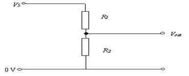
- In the diagram across if R2 is four times greater than R1; it means that the potential difference across R2 will be four times greater than the potential difference across R1 (4 times more work needed to bring the same amount of charge through both resistors).
- The total potential difference across both resistors would be the same as the potential difference between Vs and ground (the 0 Volt mark), because voltages in parallel are the same.
- In this scenario, if the supply voltage was 30 Volts, then the voltage across R1 would be 6 Volts and the voltage across R2 would be 24 Volts.
The Potentiometer
A potentiometer is a variable potential divider.
Potentiometers are variable voltage dividers with a shaft or slide control for setting the division ratio.
In the diagram for the potential divider circuit above, the voltage-out is the voltage across R2 and will only change if the temperature of R2 or R1 was to change.
A simple way to gradually vary the voltage out is to replace R1 and R2 by one variable resistor.
The output voltage is then the voltage between the ground (the bottom line above) and the middle contact.
Mandatory Experiments:
- To verify Ohm’s Law
- To Investigation the relationship between the potential difference across a filament bulb and the current through it.
- To Investigation the relationship between the resistance of a metallic conductor and temperature.
- To measure the Resistivity of the Material of a Wire.
Solving Electric Circuit Problems
Step One: Find the Total Current flowing in the circuit
- First establish the Total Voltage supplied, which causes the electrons to move. You are usually told this directly.
- Next we need to calculate the Total Resistance of the circuit.
To find total resistance you must remember the rules for adding resistors in series and adding resistors in parallel. To test yourself try page 261, no. 11. - Total Current can then be found using I = VTotal/RTotal
Step Two: Look for the isolated resistor.
- There will be one resistor on its own, so it’s easiest to start with this.
- Remember the total current will flow through this resistor, so use V = IR to find V.
Step Three: Look at remaining resistors.
- Subtract the voltage associated with the isolated resistor from the total voltage to find the voltage across the remaining resistors.
- Now use your knowledge of voltages in series and in parallel, and current in series and parallel to solve the question in hand.
To test yourself try page 250, no.12.
Now look over Problems 4 and 5, page 260 and try No.s 1 – 14, page 261, concentrating on 13 and 14.
Example
The diagram shows a number of resistors connected to a 12 V battery and a bulb whose resistance is 4 Ω.
 Calculate the current flowing through each resistor.
Solution
Step One: Find the Total Current flowing in the circuit
Total voltage = 12 V
Total resistance:
First calculate the combined resistance of the 15 Ω and 30 Ω resistors in parallel.
1/R15,30 = 1/15 + 1/30
R15,30 = 10 Ω
Total resistance of the circuit = 10 + 10 + 4 = 24 Ω
Calculate the current flowing in the circuit
I = V/R =
ITotal = VTotal/RTotal = 12/24 = 0.5 A
Step Two: Look for the isolated resistor(s).
10 Ω resistor:
I = 0.5 A, R = 10 Ω. V = IR = (0.5)(10) = 5 Volts
Lightbulb (4 Ω):
I = 0.5 A, R = 4 Ω, V = IR = (0.5)(4) = 2 Volts
Step Three: Look at remaining resistors.
V = 12 – 5 – 2 = 5 Volts, so the potential difference across both the15 Ω and the 30 Ω resistors is 5 V.
To find I use I = V/R
Current through 15 Ω resistor = 5/15= 0.33 Amps
Current through 30 Ω resistor = 5/30 = 0.17 Amps
Note that the current through the 15 Ω resistor plus the 30 Ω resistor adds up to 0.5 A, which was the current going in.
Note that you could have used ratios to split up the current: 30 is twice 15 so 2/3 of the total current goes through the 15 Ω resistor while 1/3 goes through the 30 Ω resistor.
I am reluctant to encourage this approach because students often make the mistake of putting the 2/3 through the 30 Ω and 1/3 through the 15 Ω resistor. The ratio won’t always work out to be nice simple numbers either, but if you want to go down that route it is certainly allowed.
Leaving Cert Physics Syllabus
Content |
Depth of Treatment |
Activities |
STS |
|
|
|
|
Resistance |
Definition of resistance, unit. Resistivity. |
Appropriate calculations. Use of ohmmeter, metre bridge.
Appropriate calculations. |
Practical uses of Wheatstone |
|
|
|
|
Potential |
Potential divider |
Demonstration |
Potentiometer as a variable |
TO MEASURE THE RESISTIVITY OF THE MATERIAL OF A WIRE
APPARATUS:
Length of nichrome wire, micrometer or digital calilpers, ohmmeter, metre stick.
DIAGRAM:
PROCEDURE:
- Tie a length of nichrome between the bars of the two stands as shown above. Stretch the wire enough to remove any kinks or ‘slack’ in the wire.
- Note the resistance of the leads when the crocodile clips are connected together.
- Connect the crocodile clips to the wire. Read the resistance from the ohmmeter. Subtract the resistance of the leads to get the resistance R of the wire.
- Measure the length (L) of the wire between the crocodile clips with the metre stick.
- Find the diameter (d) of the wire at different points, taking the zero error into account. Find the average value of the diameter d. We use a digital callipers instead of the micrometer.
- Calculate the resistivity using the formula

- Repeat using different lengths of wire and calculate an average value for ρ.
RESULTS:
Run no. |
Diameter d (m) |
RTotal |
RLeads |
Rnet |
L |
|
1. |
|
|
|
|
|
|
2. |
|
|
|
|
|
|
3. |
|
|
|
|
|
|
Average value for resistivity = ________________ W m.
CONCLUSION:
We found an average value for the resistivity of the wire as __________ W m.
This is reasonably accurate because all our answers are close together and are reasonably close to the accepted value of 100 × 10-8 Ω m (at 20 °C).
SOURCES OF ERROR / PRECAUTIONS:
- Ensure that the wire is straight when measuring its length.
- Measure only between the inside of the ohmmeter contacts.
- Make sure to zero the reading on the callipers before starting.
NOTE:
When setting up lay the wire over a metre stick and clamp it to using G-clamps. The length of wire can now be measured directly.
TO INVESTIGATE THE VARIATION OF THE RESISTANCE OF A METALLIC CONDUCTOR WITH TEMPERATURE
APPARATUS:
Coil of wire, glycerol, beaker, heat source, thermometer, ohmmeter, boiling tube
DIAGRAM:
PROCEDURE:
- Set up the apparatus as shown in the diagram.
- Use the thermometer to note the temperature of the glycerol, which we assume to be the same as the temperature of the coil.
- Record the resistance of the coil of wire using the ohmmeter.
- Heat the beaker and for each 10 °C rise in temperature record the resistance and temperature using the ohmmeter and the thermometer.
- Plot a graph of resistance against temperature.
RESULTS:
R (W) |
|
|
|
|
|
|
|
|
θ (0C) |
|
|
|
|
|
|
|
|
CONCLUSION:
- From the graph we can see that there is a linear relationship between the temperature of the wire and its resistance, and that as one increases so does the other.
- We believe our data to be reliable because it resulted in a straight line which the theory predicted.
PRECAUTIONS / SOURCES OF ERROR:
- Check for the resistance of the connecting leads and contacts on the ohmmeter. Subtract from later readings
- Heat very slowly to try to maintain thermal equilibrium between the water and glycerol and coil. When the bunsen is removed wait until the temperature is steady before taking the resistance readings.
- Use glycerol in the test tube as it is a better heat conductor than water.
TO INVESTIGATE THE VARIATION OF CURRENT (I) WITH P.D. (V) FOR A METALLIC CONDUCTOR AND HENCE CALCULATE THE RESISTANCE (OHM’S LAW)
APPARATUS:
Low voltage power supply, rheostat, voltmeter, ammeter, length of nichrome wire.
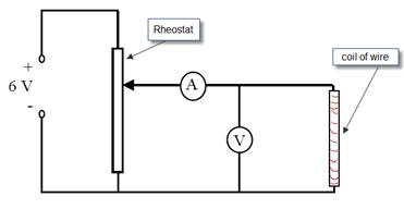
DIAGRAM:
PROCEDURE:
- Set up the circuit as shown.
- Record the potential difference (V) and the current (I) using the voltmeter and ammeter respectively.
- Adjust the potential divider to obtain different values for V and I.
- Obtain at least six values for V and I.
- Plot a graph of I against V.
- Calculate the slope of the graph.
If plotting V on the y-axis and I on the x-axis then the slope of t he graph corresponds to the resistance of the metallic conductor.
If plotting V on the x-axis and I on the y-axis then the slope of t he graph corresponds to the inverse of the resistance of the metallic conductor.
RESULTS:
V (V) |
|
|
|
|
|
|
|
I (A) |
|
|
|
|
|
|
|
CONCLUSION:
- Our graph resulted in a straight line through the origin which implies that the current is directly proportional to the potential difference.
- We believe our results to be reliable because they resulted in a straight line through the origin, as the theory predicted.
- The resistance of the wire may be determined from the reciprocal of the slope of the graph.
PRECAUTIONS:
- Use a low voltage so that the current flowing will be small enough that the temperature of the wire stays constant.
- Use a sensitive milli-ammeter and voltmeter to get accurate readings.
NOTES:
A varying voltage can be obtained from a fixed supply voltage by using a potential divider. It consists of a variable resistor or fixed resistors in series. Move the slider to change the output voltage. This results in the output voltage from the potential divider being a fraction of the input voltage.
Normally we would put V on the y-axis and I on the x-axis, and therefore the slope of the graph would correspond to the resistance. In this case however calculating the resistance is not the main focus of the experiment; the main focus is to investigate how the current depends upon the potential difference. That is why we put the independent variable (the one we have control over) on the x-axis. Hence current goes on the y-axis.
We use the same approach for all of the variations (filament bulb, copper sulphate, semi-conductor diode).
For the coil of wire you could use a separate rheostat. The two connections in this are both at the bottom.
Alternatively you could use 1 m of 26 s.w.g. nichrome wire wound on a plastic comb. This has a resistance of approximately 7.0 Ω.
TO INVESTIGATE THE VARIATION OF CURRENT (I) WITH P.D. (V) FOR A FILAMENT BULB AND
APPARATUS:
Low voltage power supply, rheostat, voltmeter, ammeter, filament bulb.
DIAGRAM:
PROCEDURE:
- Set up the circuit as shown (replace the letter X with A for ammeter above, and don’t write this into your report).
- Record the potential difference (V) and the current (I) using the voltmeter and ammeter respectively.
- Adjust the potential divider to obtain different values for V and I.
- Obtain at least six values for V and I.
- Plot a graph of I against V.
RESULTS:
V (V) |
|
|
|
|
|
|
|
I (A) |
|
|
|
|
|
|
|
CONCLUSION:
- As the potential difference across the bulb increases so does the current, but not in a linear fashion therefore the two are not directly proportional.
- We believe our results to be reliable because they resulted in a smooth curve, as the theory predicted.
QUESTION:
- Why does the graph start to level off at the end?
- Why does this happen for the filament bulb but not for the coil of wire (metallic conductor) in the last experiment?
NOTES:
A varying voltage can be obtained from a fixed supply voltage by using a potential divider. It consists of a variable resistor or fixed resistors in series. Move the slider to change the output voltage. This results in the output voltage from the potential divider being a fraction of the input voltage.
Extra Credit
*Ohm’s Law
Remember from Junior Cert that a resistor was defined as something which resists the flow of current? Well in Leaving Cert Physics we like to quantify things (that means put numbers on them), hence the formula.
If you think about it the formula does make sense, because if V is small (you use a small effort to push the electrons through) and you find that I (the current) is large, this suggests that there couldn’t have been much resistance in the circuit, i.e. if the ratio of Voltage to Current is small, so is the Resistance.
Similarly, if you use a lot of energy to try and push the electrons through (V is large), and yet you still only get a small current (I is small), this suggests that there must be a large resistance in the circuit, i.e. if the ratio of Voltage to Current is large, so is the Resistance.
“What power! To condense all the meaning in that long sentence into a simple four symbol equation. That is the art of our science.”
“at Constant Temperature”
In practice most metals heat up when a current passes through them, which means that the resistance increases.
This is because the atoms in the metal gain energy and ‘jiggle’ up and down, making it harder for the electrons to get by.
Note that if you omit the phrase ‘at constant temperature’ you will lose 3 marks out of the total 6.
*Resistors in Series and Resistors in Parallel derivations
The key here is to begin by putting the R on same side of the equation as the variable which is constant for that particular section.
Because this variable is constant it can then be cancelled across the line.
*Resistivity
Why do we have a concept called ‘resistivity’?
Because you can’t just say that ‘the resistance of copper is 3 Ohms’; you would need to specify the length and the width of the material. It’s similar to the reason why we have the concept of Density. It wouldn’t make any sense to say that iron is heavier than paper, because you might have a tiny piece of iron and a very large piece of paper (say a Golden Pages directory). What we mean when we say that iron is heavier than paper is ‘if we have the same volume of both, then the iron would have a greater mass’. Density is a shorthand way of saying this.
In a similar way, saying that the resistivity of copper is greater than that the resistivity of silver is shorthand for saying; ‘If the two materials are of equal length and equal cross-sectional area, then silver would have a greater resistance than copper’.
*The formula for resistivity is![]()
From the following;
The resistance of a material is proportional to the length Þ R µ l
The resistance of a material is inversely proportional to the Cross Sectional Area (C.S.A.) Þ R µ 1/A Putting this together Þ R = k l/A
The proportional constant is given the symbol r (rho– same as for density); ![]()
Cross-multiplying to get r on its own; ![]()
I have something called ‘Silly Putty’ which is used to demonstrate the relationship between Resistance, length and C.S.A.; Remind me to demonstrate it.
Resistivities of some common metals (You don’t need to know these)
Silver : 1.6 × 10⁻⁸ Ωm
Copper: 1.7 × 10⁻⁸ Ωm
Nichrome: 1 × 10⁻⁶ Ωm
*Measuring resistance using a Wheatstone Bridge
The concept of the Wheatstone Bridge is very useful for students to test their understanding of electricity.
If you can understand this you can understand everything else in electricity.
Note that we have two currents beside each other, both flowing in the same direction.
Now even if one current is much larger than the other, they can still be connected up and no current will flow from one to the other.
If this is the case then we can conclude that the potential is the same at both ends of the connecting wire.
Another way to say this is to say that the potential difference between the two points is zero.
The galvanometer in the middle is used to detect current.
If it reads zero then no current flows between the two points.
We say that the bridge is balanced.
The following analogy, inspired by my predecessor Mr Dave Clarke, is very helpful.
Consider two streams flowing parallel to each other.
One is carrying much more water than the other.
Now both streams are connected by a channel at a certain point.
The channel is full of water. A leaf is now placed in the middle of this channel.
If the leaf doesn't move, what can we deduce about the two streams?
First off, if the leaf isn't moving, then the water in the channel isn't moving.
Secondly, water always flows from a higher point to a lower point, so if the water in the channel isn't moving, then both ends of the channel must be at the same height.
NB: This conclusion is still valid even if there is much more water flowing in one stream than the other.
Another way of saying that both points are at the same height is to say that the height difference between the two points is zero.
Now let's go back and try again to understand the Wheatstone bridge:
The galvanometer in the middle is used to detect current.
If it reads zero then no current flows between the two points.
We say that the bridge is balanced.
Now the key to this is to realise that not only can the bridge be balanced when there is a current flowing on either side, but the currents on either side need not be the same, indeed it would be rare that they were.
Now just like water flows from a high to a low point (in a gravitational field), current will flow from a high potential to a low potential.
The terms here can be confusing.
Remember that 'potential difference' means the work done in bringing charge from one place to another, but 'potential at a point' refers to the work done in bringing charge from the earth to that point.
Now refer back to the textbook for the derivation (you are not required to know this).
Exam Questions
- [2007][2005]
Define resistance
- [2005 OL][2006 OL][2007 OL][2010 OL]
State Ohm’s Law
- [2006 OL]
Name the electrical component represented in the diagram.
- [2008 OL]
Give two uses for the instrument shown on the far right.

- [2007 OL]
The circuit diagram shows two resistors connected in series with a 6 V battery.
- Calculate the total resistance of the circuit.
- Calculate the current in the circuit.
- Calculate the potential difference across the 9 Ω resistor.
 [2005 OL]
The circuit diagram shows a 100 Ω resistor and a thermistor connected in series with a 6 V battery.
At a certain temperature the resistance of the thermistor is 500 Ω.
- Calculate the total resistance of the circuit.
- Calculate the current flowing in the circuit.
- Calculate the potential difference across the 100 Ω resistor.
- As the thermistor is heated, what happens to the resistance of the circuit?
- As the thermistor is heated, what happens to the potential difference across the 100 Ω resistor?
- [2002 OL]
- A circuit consists of a 3 Ω resistor and a 6 Ω resistor connected in parallel to a 1.5 V d.c. supply as shown. Calculate the total resistance of the two resistors.
- Calculate the current flowing in the circuit.
- What is the current in the 3 Ω resistor?
 [2010 OL]
- The diagram shows a number of resistors connected to a 12 V battery and a bulb whose resistance is 4 Ω.
Calculate the combined resistance of the 15 Ω and 30 Ω resistors in parallel.
- Calculate the total resistance of the circuit
- Calculate the current flowing in the circuit
- [2008 OL]
- The two headlights of a truck are connected in parallel to a 24 V supply.
Draw a circuit diagram to show how the headlights are connected to the supply.
- What is the advantage of connecting them in parallel?
- Why should a fuse be included in such a circuit?
- The resistance of each headlight is 20 Ω. Calculate the total resistance in the circuit.
- Calculate the current flowing in the circuit.
- [2005]
- Two resistors, of resistance R1 and R2 respectively, are connected in parallel.
Derive an expression for the effective resistance of the two resistors in terms of R1 and R2.
- In the ciruit diagram, the resistance of the thermistor at room temperature is 500 Ω.
At room temperature calculate the total resistance of the circuit.
- At room temperature calculate the current flowing through the 750 Ω resistor.
- As the temperature of the room increases, explain why the potential at A increases.
- [2006]
Explain why the resistance of the bulb is different when it is not connected to the mains.
- [2005 OL]
- The graphs show how current (I ) varies with potential difference (V) for (a) a metal, (b) a filament bulb.
Which conductor obeys Ohm’s law?
- Explain your answer.
- [2003]
Draw a graph to show the relationship between current and voltage for a metal at constant temperature.
- [2008][2007][2002]
Define resistivity.
- [2008]
Give the unit of resistivity.
- [2002]
The total length of the cables connecting the industrial park to the power station is 15 km. The cables have a diameter of 10 mm and are made from a material of resistivity 5.0 × 10⁻⁸ Ω m.
Calculate the total resistance of the cables.
- [2008]
A toaster has a heating coil made of nichrome which it has a resistance of 12 Ω.
The coil is 40 m long and it has a circular cross-section of diameter 2.2 mm.
Calculate the resistivity of nichrome.
- [2010]
A hair dryer with a plastic casing uses a coiled wire as a heat source. When an electric current flows through the coiled wire, the air around it heats up and a motorised fan blows the hot air out.
 The diagram shows a basic electrical circuit for a hair dryer.
Describe what happens when switch A is closed and the rheostat is adjusted
- Describe what happens when switch A and switch B are closed.
Current flows through coil and the coil gets hot.
- Calculate the current that flows through the coil when the dryer is turned on.
- The maximum power generated in the heating coil is 2 kW.
What is the initial resistance of the coil?
- A length of nichrome wire of diameter 0.17 mm is used for the coil.
Calculate the length of the coil of wire.
- Explain why the current through the coil would decrease if the fan developed a fault and stopped working.
 [2007]
A metre bridge was used to measure the resistance of a sample of nichrome wire.
The diagram indicates the readings taken when the metre bridge was balanced.
The nichrome wire has a length of 220 mm and a radius of 0.11 mm.
- Calculate the resistance of the nichrome wire
- Calculate the resistivity of nichrome
- Sketch a graph to show the relationship between the temperature and the resistance of the nichrome wire as its temperature is increased.
- What happens to the resistance of the wire as its temperature falls below 0oC?
- What happens to the resistance of the wire as its length is increased?
- What happens to the resistance of the wire if its diameter is increased?
- Name another device, apart from a metre bridge, that can be used to measure resistance.
- Give one advantage and one disadvantage of using this device instead of a metre bridge.
Mandatory Experiments
- [2003 OL]
 The diagram shows the circuit used by a student to investigate the variation of current with potential difference for a filament bulb.
- Name the apparatus X. What does it measure?
- Name the apparatus Y. What does it do?
The table shows the values obtained for the current and the potential difference during the experiment.
Potential difference /V |
2.0 |
3.0 |
4.0 |
5.0 |
6.0 |
7.0 |
8.0 |
9.0 |
Current /A |
1.0 |
1.5 |
1.9 |
2.3 |
2.6 |
2.9 |
3.2 |
3.5 |
- Draw a graph, on graph paper, of the current against the potential difference.
- Use your graph to find the resistance of the bulb when the current is 3 A.
- The resistance of the bulb is 2.0 Ω when the current is 1.5 A
Explain why the resistance of the bulb when the current is 1.5 A is different from its resistance when the current is 3 A.
 [2005]
A student investigated the variation of the current I flowing through a filament bulb for a range of different values of potential difference V.
- Draw a suitable circuit diagram used by the student.
- Describe how the student varied the potential difference.
- The student drew a graph, as shown, using data recorded in the experiment.
With reference to the graph, explain why the current is not proportional to the potential difference.
- With reference to the graph, calculate the change in resistance of the filament bulb as the potential difference increases from 1 V to 5 V.
- Give a reason why the resistance of the filament bulb changes.
- [2005 OL}
resistance of the wire/ Ω |
26.4 |
|
|
length of the wire /mm |
685 |
|
|
diameter of the wire /mm |
0.20 |
0.19 |
0.21 |
In an experiment to measure the resistivity of the material of a wire, a student measured the length, diameter and the resistance of a sample of nichrome wire.
The table shows the measurements recorded by the student.
- Describe how the student measured the resistance of the wire.
- Name the instrument used to measure the diameter of the wire.
- Why did the student measure the diameter of the wire in three different places?
- Using the data, calculate the diameter of the wire.
- Hence calculate the cross-sectional area of the wire. (A = πr2)
- Calculate the resistivity of nichrome using the formula ρ = RA/L
- Give one precaution that the student took when measuring the length of the wire.
- [2010 OL]
R/Ω |
20.2 |
|
|
l/cm |
48.8 |
|
|
d/mm |
0.21 |
0.20 |
0.18 |
In an experiment to determine the resistivity of the material of a wire, a student measured the length, diameter and resistance of a sample of nichrome wire.
The table shows the data recorded by the student.
- Describe how the student measured the resistance of the wire.
- Describe how the length of the wire was measured.
- What instrument did the student use to measure the diameter of the wire?
- Why did the student measure the diameter of the wire at different places?
- Using the data, calculate the cross-sectional area of the wire.
- Find the resistivity of nichrome.
- [2009]
In an experiment to measure the resistivity of nichrome, the resistance, the diameter and appropriate length of a sample of nichrome wire were measured.
The following data were recorded:
Resistance of wire = 7.9 Ω
Length of wire = 54.6 cm
Average diameter of wire = 0.31 mm
- Describe the procedure used in measuring the length of the sample of wire.
- Describe the steps involved in finding the average diameter of the wire.
- Use the data to calculate the resistivity of nichrome.
- The experiment was repeated on a warmer day. What effect did this have on the measurements?
- [2004]
The following is part of a student’s report of an experiment to measure the resistivity of nichrome wire.
“The resistance and length of the nichrome wire were found. The diameter of the wire was then measured at several points along its length.”
The following data was recorded.
Resistance of wire = 32.1 Ω
Length of wire = 90.1 cm
Diameter of wire = 0.19 mm, 0.21 mm, 0.20 mm, 0.21 mm, 0.20 mm
- Name an instrument to measure the diameter of the wire and describe how it is used.
- Why was the diameter of the wire measured at several points along its length?
- Using the data, calculate a value for the resistivity of nichrome.
- Give two precautions that should be taken when measuring the length of the wire.
- [2006 OL]
In an experiment to investigate the variation of resistance with temperature for a metallic conductor in the form of a wire, a student measured the resistance of the conductor at different temperatures. The table shows the measurements recorded by the student.
Temperature / oC |
20 |
30 |
40 |
50 |
60 |
70 |
80 |
Resistance / Ω |
45.6 |
49.2 |
52.8 |
57.6 |
60.0 |
63.6 |
68.4 |
- How did the student measure the resistance of the wire?
- Describe, with the aid of a diagram, how the student varied the temperature of the wire.
- Using the data in the table, draw a graph on graph paper of the resistance of the conductor against its temperature. Put temperature on the horizontal axis (X-axis).
- Use the graph to estimate the temperature of the conductor when its resistance is 50 Ω.
- What does your graph tell you about the relationship between the resistance of a metallic conductor and its temperature?
- [2008]
A student investigated the variation of the resistance R of a metallic conductor with its temperature θ.
θ/oC |
20 |
30 |
40 |
50 |
60 |
70 |
80 |
R/Ω |
4.6 |
4.9 |
5.1 |
5.4 |
5.6 |
5.9 |
6.1 |
The student recorded the following data.
- Describe, with the aid of a labelled diagram, how the data was obtained.
- Draw a suitable graph to show the relationship between the resistance of the metal conductor and its temperature.
- Use your graph to estimate the resistance of the metal conductor at a temperature of –20 oC.
- Use your graph to estimate the change in resistance for a temperature increase of 80 oC.
- Use your graph to explain why the relationship between the resistance of a metallic conductor and its temperature is linear.
Exam Solutions
- The resistance of a conductor is the ratio of the potential difference across it to the current flowing through it.
- Ohm’s Law states that the current flowing through a conductor is directly proportional to the potential difference across it, assuming constant temperature.
- Variable resistor / rheostat / potentiometer
- It is a multi-meter so it can function as a voltmeter, ammeter or ohmmeter.
- R = 3 + 9 = 12 Ω
- V=IR Þ I = V/R = 6/12 = 0.5 A
- V = I R = 0.5 × 9 = 4.5 V
- RTotal = R1 + R2 Þ RTotal = 100 + 500 = 600 Ω.
- V = I R Þ I = V/R ÞI = 6/600 = 0.01A
- V = I R Þ V = 0.01 ×100 ÞV = 1 V.
- It decreases.
- {This part was ridiculously tricky for ordinary level}
It increases, because the total voltage is still 6 V and this is the potential difference across both resistors combined, so if the potential difference decreases across the thermistor, it must increase across the 100 Ω resistor.

- For resistors in parallel we use the formula
1/R = 1/3 + 1/6 Þ 1/R = 1/2 Þ R = 2 Ω.
- V = IR Þ I = V/R Þ I = 1.5/2 = 0.75 A
- Voltages in parallel are the same and the supply voltage is in parallel with the 3 Ω resistor, so the voltage across the 3 Ω resistor is also 1.5 Volts Þ I = 1.5/3 = 0.5 A
- 1/R15,30 = 1/15 + 1/30
R15,30 = 10 Ω
- Total resistance = 10 + 10 + 4 = 24 Ω
- I = V/R = 12/24 = 0.5 A
- Circuit diagram showing battery and two bulbs connected in parallel.
- If one goes the other still works, they are brighter.
- To prevent too high a current flowing.

Þ 1/RT = 1/20 + 1/20 = 1/10 Þ 1/RT = 1/10 Þ RT = 10 Ω
- V = IR Þ I = V/R Þ I = 24/10 = 2.4 A.
- IT = I1 + I2
(apply Ohm’s law ) V = IR
V/RT= V/R1+ V/R2
1/RT= 1/R1+ 1/R2
- 1/Rp = 1/500 + 1/750
Rp = 300 Ω
RTot = 600 Ω
- ITotal = (VTot / RTot) = 6 ÷ 600 = 0.01 A
V300 = (0.01)(300) = 3 V Þ Vp = 6 – 3 = 3 V.
I750 = 3 ÷ 750 = 4 × 10⁻³ A = 4 mA
- The resistance of thermistor (and 750 Ω combination) decreases
Therefore potential difference across thermistor and 750 Ω combination decreases
Therefore potential at A increases
- Cold filament has lower resistance
- The metal.
- Graph (a) results in a straight line through the origin, therefore I is proportional to V
- See graph
- The resistivity of a material is defined as the resistance of a cube of material of side 1 metre.
- The unit of resistivity is the ohm metre (W m)
- A = πr2 = π(.005)2
r = RA/l Þ R = rl/A Þ R = (5.0 × 10⁻⁸)(15000)/ π(.005)2 Þ R = 9.6 W
![]()
Þ r = 12 × π (1.1 × 10⁻³)2 / 40 = 1.14 × 10⁻⁶ Ω m.
- The fan operates and its speed of rotation changes.
- Current flows through coil and the coil gets hot.
The fan blows hot air
- P = VI
I = P/V = 2000/230
I = 8.7 A
- V = RI
R = 230/8.7 = 26.4 Ω
- A = πr2
A = (3.14)(0.085 × 10⁻³)2
A = 2.27 × 10⁻⁸ m2
ƿ = RA/l
l = RA/ ƿ
l = (26.4)( 2.27 × 10⁻⁸)/(1.1 × 10-6)
l = 0.545 m
- The coil gets hot therefore its resistance increases (or any correct statement explaining why Rcct or Rcoil has increased).
- R1/R2= L1/L2
R/20 = 282/718
R = 7.86 Ω
- ρ =RA/L
ρ = (7.844)(3.801× 10⁻⁸)/ 0.220
ρ = 1.36 × 10⁻⁶ Ω m
- Axes labelled R and T (or θ)
Correct linear graph with intercept showing R greater than zero.
- R decreases
- R increases
- R decreases
- Ohmmeter / wheatstone bridge /multimeter.
- Ohmmeter: compact, portable, faster method, etc. less accurate, fragile, difficult to calibrate/chec
Wheatstone bridge: compact, portable, more accurate etc. ‘black box’ difficult to comprehend, expensive.
- X is an ammeter. It measures current.
- Y is a voltmeter. It measures volts.
- See graph
- When the current is 3 A the voltage is 7.2 V, so using V = IR results in R = 2.4 W.
- Because the resistance of the bulb increases with temperature, and temperature is greater when the current is greater.
 See diagram
- By adjusting the voltage on the power supply.
- Because the graph is not a straight line.
- At 1 V: R = V/I = 1/0.028 = 35.7 Ω
At 5 V: R = (5/0.091) = 54.9 Ω
Change in resistance (= 54.9 – 35.7) = 19.2 Ω
- As current increases the temperature of filament increases, therefore the filament gets hotter and it gets more difficult for electrons to pass through due to increased vibration of the metal atoms.
- Using an multimeter set to measure resistance, the ends of the multimeter wire were connected to the ends of the wire in question.
- A digital callipers.
- To calculate an average diameter because the diameter of the wire is not uniform.
- Average diameter = (0.20 + 0.19 + 0.21)/3 Þ diameter = 0.60 ÷ 30 Þ diameter = 20 mm
- r = 0.1 mm = 0.0001 m
A = πr2 ÞA = π (0.0001)2
A = 3.14 × 10⁻⁸ m2
- ρ = (26.4)( 3.14 × 10⁻⁸) ÷ 0.685
ρ = 1.21 × 10⁻⁶ Ω m.
- Avoid parallax error when using metre stick, keep wire straight (no kinks), measure only the length of wire between leads to ohmmeter.
- Ohmmeter / (digital) multimeter / measure V and I and hence determine R
- Ensure the wire is taut and measure the length between the crocodile clips using a metre-stick.
- Micrometer / digital callipers
- To get average (diameter) as wire may not be uniform
- Average diameter = 0.197 mm Þ r = 0.0001m
A = π(0.1 × 10⁻³)2
A = 3.03 – 3.14 × 10⁻⁸ m2
- Ƿ = RA/l
Ƿ = (20.2)(3.14 × 10⁻⁸)/(0.488)
Ƿ = 1.25 – 1.29 × 10⁻⁶ Ω m)
- Straighten the wire, clamp it to a bench and measure the distance between the points for which the resistance was measured.
- Zero the micrometer / digital callipers
- Place wire between jaws
- Tighten jaws and take reading
- Repeat at different points on wire
- Get average diameter
- A = πr2 Þ A = π(0.155 × 10⁻³)2 = 7.55 × 10⁻⁸ m2
r = RA/l Þ r = (7.9)(7.55 × 10⁻⁸)/0.546) Þ r = 1.09 × 10⁻⁶ Wm
- Resistance increased / length increased (or wire expands) / diameter increased
- Digital callipers
Place the wire between the jaws
Tighten the jaws
Read the callipers
- To get an average because the material is not of uniform density.
- Average diameter = 0.202 mm
A = πr 2 = 3.2 ×10⁻⁸ m2
ρ =RA/L
ρ = (32.1)(3.2 × 10⁻⁸)/0.901)
ρ = 1.1×10⁻⁶ Ω m
- Ensure no kinks in wire, only measure length whose R value was measured, avoid parallax error, etc.
 By using a multimeter set to measure resistance.
- See diagram.
The temperature was varied by allowing the wire to be heated.
 See graph
- Use the graph to estimate the temperature of the conductor when its resistance is 50 Ω.
 What does your graph tell you about the relationship between the resistance of a metallic conductor and its temperature?
- The resistance was read from the ohmmeter, the temperature was read from the thermometer and the readings were varied using the heat source.
- See graph
- Continue (extrapolate) the graph on the left hand side and then read off the resistance value that corresponds to the temperature of – 20 0C.
R = 3.6 Ω
- y-intercept value ≈ 4.12 Ω Þ change in resistance ≈ 2 Ω
- A straight line is obtained.
Source : http://www.thephysicsteacher.ie/LC%20Physics/Student%20Notes/23.%20Resistance.doc
Web site link: http://www.thephysicsteacher.ie
Author : not indicated on the source document of the above text
If you are the author of the text above and you not agree to share your knowledge for teaching, research, scholarship (for fair use as indicated in the United States copyrigh low) please send us an e-mail and we will remove your text quickly.
Resistance
Resistance
Resistance
This is the right place where find the answers to your questions like :
Who ? What ? When ? Where ? Why ? Which ? How ? What does Resistance mean ? Which is the meaning of Resistance?
Resistance physics notes
Alanpedia.com from 1998 year by year new sites and innovations
Main page - Disclaimer - Contact us